Writing an Embedded Rust Driver for the DHT22
The DHT22, also known as AM2302, is a digital sensor used for measuring both temperature and humidity. If you're building a device that needs to detect environmental conditions like room temperature or humidity levels, this sensor is a great choice. You can easily purchase it online from stores at an affordable price. The older version is DHT11 which is slighly less accurate than DHT22.
The DHT22 uses a capacitive humidity sensor and a thermistor to measure the surrounding air. It then sends this data as a digital signal over a single data line, so you do not need any analog input pins.
Here are some key features of the DHT22:
- Measures humidity from 0 to 100 percent RH with 2 to 5 percent accuracy
- Measures temperature from -40 to +80 degrees Celsius with around ±0.5 degree accuracy
- Communicates over a single-wire digital protocol
In this chapter, we will learn how to write a driver for this sensor. I chose the DHT22 because it uses a simple communication method, making it suitable for learning how to write embedded Rust drivers. It is also low-cost and widely available.
Note: While we're building our own driver from scratch for educational purposes, there are already existing crates available for the DHT22 sensor, such as dht-sensor. You can also explore those crates.
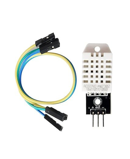
DHT22 Sensor and Module
The DHT22 is available in two forms: the bare sensor and a ready-to-use module. The bare sensor comes in a 4-pin package, but only three of those pins are needed. The module version is typically provided with just three pins, which are the ones actually needed for operation.
- VCC - Connects to 3.3V or 5V
- Data - Signal pin connected to a GPIO (pull-up resistor is already present on the board)
- GND - Ground
One important difference between the DHT22 module and the bare sensor is the presence of an onboard pull-up resistor. On the module, this resistor is already connected between the data line and VCC, ensuring that the line reliably returns to a HIGH state when neither the microcontroller nor the sensor is actively pulling it LOW. This is essential for correct timing and stable communication.
If you're using the raw 4-pin DHT22 sensor (without a breakout board), it does not include a pull-up resistor. In that case, you'll need to add an external resistor (typically 10kΩ) between the data pin and VCC to ensure proper operation.