Rust Embedded Drivers (RED) Book
In this book, we will learn how to create simple drivers for hardware devices that work within the embedded Rust ecosystem.
Prerequisites
- Rust basics: You should have a basic understanding of Rust. This book doesn't cover the fundamentals of the language. If you're new to Rust, I recommend starting with the official Rust book. You can also find other resources here.
This book is slightly more advanced than the others in the "impl Rust for" series and is intended for readers who already have some basic experience with embedded Rust.
If you're a beginner and haven't read the other books yet, you may want to start with one of the following:
- esp32.implrust.com - impl Rust for ESP32 (uses the ESP32 Devkit v1)
- mb2.implrust.com - impl Rust for micro:bit v2
- pico.implrust.com - impl Rust for Raspberry Pi Pico (RP2350)
Other Learning Resources
- The Embedded Rust Book : This is a great resource if you're just getting into embedded Rust. You don't have to read it before jumping into this book, but it's a good place to start. I'll do my best to explain things as we go, but if I miss something or don't cover it clearly, this book can really come in handy. One way or another, I definitely recommend giving it a read.
License
The "Rust Embedded Drivers" book(this project) is distributed under the following licenses:
- The code samples and free-standing Cargo projects contained within this book are licensed under the terms of both the MIT License and the Apache License v2.0.
- The written prose contained within this book is licensed under the terms of the Creative Commons CC-BY-SA v4.0 license.
Support this project
You can support this book by starring this project on GitHub or sharing this book with others 😊
Disclaimer:
The experiments and projects shared in this book have worked for me, but results may vary. I'm not responsible for any issues or damage that may occur while you're experimenting. Please proceed with caution and take necessary safety precautions.
Writing an Embedded Rust Driver for the DHT22
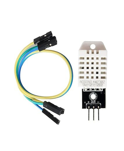
The DHT22, also known as AM2302, is a digital sensor used for measuring both temperature and humidity. If you're building a device that needs to detect environmental conditions like room temperature or humidity levels, this sensor is a great choice. You can easily purchase it online from stores at an affordable price. The older version is DHT11 which is slighly less accurate than DHT22.
The DHT22 uses a capacitive humidity sensor and a thermistor to measure the surrounding air. It then sends this data as a digital signal over a single data line, so you do not need any analog input pins.
Here are some key features of the DHT22:
- Measures humidity from 0 to 100 percent RH with 2 to 5 percent accuracy
- Measures temperature from -40 to +80 degrees Celsius with around ±0.5 degree accuracy
- Communicates over a single-wire digital protocol
In this chapter, we will learn how to write a driver for this sensor. I chose the DHT22 because it uses a simple communication method, making it suitable for learning how to write embedded Rust drivers. It is also low-cost and widely available.
Note: While we're building our own driver from scratch for educational purposes, there are already existing crates available for the DHT22 sensor, such as dht-sensor. You can also explore those crates.
DHT22 Sensor and Module
The DHT22 is available in two forms: the bare sensor and a ready-to-use module. The bare sensor comes in a 4-pin package, but only three of those pins are needed. The module version is typically provided with just three pins, which are the ones actually needed for operation.
- VCC - Connects to 3.3V or 5V
- Data - Signal pin connected to a GPIO (pull-up resistor is already present on the board)
- GND - Ground
One important difference between the DHT22 module and the bare sensor is the presence of an onboard pull-up resistor. On the module, this resistor is already connected between the data line and VCC, ensuring that the line reliably returns to a HIGH state when neither the microcontroller nor the sensor is actively pulling it LOW. This is essential for correct timing and stable communication.
If you're using the raw 4-pin DHT22 sensor (without a breakout board), it does not include a pull-up resistor. In that case, you'll need to add an external resistor (typically 10kΩ) between the data pin and VCC to ensure proper operation.
How the DHT22 Sensor Communicates Over a Single Wire
The DHT22 communicates with the microcontroller using a custom single-wire protocol. It uses only one data line for transferring data. The microcontroller must follow strict timing rules to read the temperature and humidity data correctly from the sensor.
So, where do we get these details? From the datasheet. If you are moving beyond basic examples in embedded programming, learning how to read datasheets is an important skill.
To be honest, the first time I looked at a microcontroller datasheet, it felt scary. Even now, I still find them a bit overwhelming - just slightly less than before. But once you start using them regularly, it gets easier. The good thing is that sensor datasheets are usually much simpler compared to full MCU datasheets.
You can find the DHT22 datasheet here. It describes how the communication between the DHT22 sensor and the microcontroller works. But I have to admit, the explanation is a bit cryptic and not very beginner-friendly. So, I will try to break it down step by step and explain the communication process in a simpler way.
Communication Overview
Here's a high-level view of the communication between the MCU and the DHT22:
+-----------+           +--------+
|   MCU     |           | DHT22  |
+-----------+           +--------+
      |                      |
      |--- Start Request --->|
      |                      |
      |<---- Response -------|
      |                      |
      |<-- 40-bit Data ------|
      |                      |
      |<- Transmission Ends -|
      |                      |
      |   Idle / Processing  |
      |                      |
The diagram above shows the high-level flow of communication between the microcontroller (MCU) and the DHT22 sensor. The process begins with the MCU sending a start request by pulling the data line low for a specified duration. This signals the DHT22 to begin its response. The sensor then replies with a short response signal, indicating it is ready to transmit data.
Following that, the DHT22 sends 40 bits of data which include humidity, temperature, and a checksum for validation. Once all bits are transmitted, the sensor sends an end signal and then releases the line. The communication ends with the bus returning to an idle high state.
Communication Sequence
The diagram below shows how the MCU and the DHT22 sensor talk to each other using just one data wire. This communication follows a specific pattern. If the timing is wrong, the data might not be received correctly.

-
Idle State
The data line is initially in an idle HIGH state, held high by a pull-up resistor. -
Start Signal (MCU to DHT22)
The microcontroller begins communication by pulling the line LOW for at least 1 ms. This tells the DHT22 to prepare for data exchange. -
MCU Release (20-40 us HIGH)
After the LOW signal, the MCU releases the line. It goes HIGH for 20 to 40 microseconds, indicating that the MCU is ready to receive a response. -
Sensor Response (DHT22 to MCU)
The DHT22 responds by pulling the line LOW for 80 us, then HIGH for 80 us. This signals the beginning of the sensor's data transmission. -
Data Transmission - 40 Bits
The sensor sends a total of 40 bits of data, which are divided into three parts: 16 bits represent the humidity value, 16 bits represent the temperature value, and the remaining 8 bits are used as a checksum to verify data integrity.Each bit starts with a 50 us LOW pulse. After that:
- If the line is HIGH for ~26-28 us, the bit is a 0
- If the line is HIGH for ~70 us, the bit is a 1
-
End of Transmission
After sending all 40 bits, the DHT22 pulls the line LOW for about 50 us, then releases it. The line goes HIGH and remains idle.
Data Bits
Once the DHT22 completes its initial response, it sends a total of 40 bits of data to the microcontroller. These 40 bits are structured as five consecutive bytes, transmitted one bit at a time over the single-wire bus. The data is sent most significant bit (MSB) first.
Relative Humidity Value
The first two bytes represent the humidity value. The first byte is the high byte (most significant 8 bits) and the second is the low byte. Together, they form a 16-bit unsigned integer. To convert this to a percentage, the value must be divided by 10. For example, if the bytes are 0x01 and 0x90, the raw 16-bit value is 0x0190, which equals 400 in decimal. Dividing by 10 gives a humidity reading of 40.0%.
Temperature Value
The next two bytes represent the temperature, again as a 16-bit value with the high byte first. This value is also divided by 10 to get the temperature in Celsius. For instance, if the temperature bytes are 0x00 and 0xFA, the combined value is 0x00FA or 250 in decimal, giving a temperature of 25.0°C. If the most significant bit of the temperature high byte is set (i.e., bit 15 is 1), it indicates a negative temperature. In that case, the temperature value should be interpreted as a signed 16-bit number, and the final result divided by 10 will be negative.
Checksum
The fifth and final byte is a checksum. This is used to verify that the data was received correctly. The checksum is calculated by summing the first four bytes and taking only the least significant 8 bits of the result (i.e., modulo 256). If the checksum sent by the sensor matches the calculated value, the data is considered valid.
Here is an example of a full 40-bit transmission represented in ASCII bit layout:
+--------+--------+--------+--------+--------+
|00000001|10010000|00000000|11111010|10001011|
+--------+--------+--------+--------+--------+
HumidH   HumidL   TempH    TempL     CRC

(0x01)   (0x90)   (0x00)   (0xFA)   (0x8B)
In this example, the humidity is 40.0%, the temperature is 25.0°C, and the checksum byte 0x8B matches the calculated sum: 0x01 + 0x90 + 0x00 + 0xFA = 0x18B.
Since the checksum is only one byte (8 bits), we only care about the lower 8 bits of this sum. To extract them, we apply a bitwise AND with 0xFF, which keeps just the least significant byte: 0x18B & 0xFF = 0x8B. This result matches the checksum sent by the sensor; on the microcontroller side(in our driver), we can perform this check to ensure the data was received correctly.
In Rust, instead of summing the values as a larger type like u16 and then applying a bitwise AND with 0xFF, we can just use wrapping_add function, which automatically keeps the result within 8 bits by discarding any overflow. Since our incoming data is already u8, using wrapping_add is more efficient and better suited for our case.
For example:
fn main() {
    let data: [u8; 4] = [0x01, 0x90, 0x00, 0xFA];
    let expected_checksum: u8 = 0x8B;

    let calculated_checksum = data.iter().fold(0u8, |sum, v| sum.wrapping_add(*v));
    println!("calculated checksum: 0x{:02X}", calculated_checksum);
    println!("is valid: {}", expected_checksum == calculated_checksum);
}
Handling Negative Temperatures
The DHT22 encodes negative temperatures using the most significant bit (MSB) of the 16-bit temperature value as a sign bit. If this bit is set (i.e., bit 15 of the 16-bit value is 1), the temperature is negative. To extract the correct value, you must first detect the sign, then mask off the sign bit and apply the negative sign after conversion.
For example, suppose the DHT22 returns the following two bytes for temperature:
Temp High Byte: 10000000 (0x80)
Temp Low Byte:  00001010 (0x0A)
Combined, these form the 16-bit value 0x800A. The MSB is 1, indicating a negative temperature.
To compute the temperature:
Mask off the sign bit: 0x800A & 0x7FFF = 0x000A
Mask off sign bit calculation represented with binary for better clarity

   10000000 00001010   (original, 0x800A)
&  01111111 11111111   (mask,     0x7FFF)
----------------------
   00000000 00001010   (result,   0x000A)
Convert to decimal: 0x000A = 10
Divide by 10: 10 / 10 = 1.0
Apply the sign: -1.0 °C
So, this bit sequence indicates a temperature of –1.0 °C.
Create Project
Now that we have a solid understanding of the DHT22 sensor's communication protocol and data format, let's begin implementing the driver in Rust for a no_std environment.
We'll start by creating a new Rust library crate. This crate will be minimal and portable, relying only on embedded-hal traits so it can run on any platform that implements them.
Create new library
cargo new dht22-sensor --lib
cd dht22-sensor
This creates a basic Rust library named dht22-sensor with a src/lib.rs entry point.
Mark the Crate as no_std
To make our library compatible with embedded systems that don't have access to the standard library, we need to mark it as no_std.
Open the src/lib.rs file, remove all lines and add the following line at the very top:
#![allow(unused)]
#![cfg_attr(not(test), no_std)]
fn main() {
}
This tells the Rust compiler to avoid linking the standard library when we are not running tests. Instead, the crate will rely only on the core crate, which provides essential Rust features like basic types and operations. As a result, we won't be able to use any features from the std crate - only what's available in core.
The cfg_attr is a conditional attribute. It means "if not testing, then apply no_std." This way, we can still write normal unit tests using std, but the compiled library will work in no_std environments.
Add Dependencies
Next, open Cargo.toml and add the embedded-hal crate under [dependencies]. This allows your driver to work with any compatible GPIO or delay implementation:
[dependencies]
embedded-hal = "1.0.0"
Optional: defmt Logging Support
We also add optional defmt support so that our driver can integrate with the defmt logging ecosystem.
To enable this, users must explicitly activate the defmt feature.
Add the following to your Cargo.toml:
Defmt
defmt = { version = "1.0.1", optional = true }

[features]
defmt = ["dep:defmt"]
Goal
By the end of this tutorial, we will have the following file structure for our DHT22 driver. While this is a relatively simple driver and could be implemented entirely in lib.rs, we prefer a more modular structure for clarity and maintainability.
The lib.rs file is the main entry point of a Rust library crate. When someone adds your crate as a dependency and uses use your_crate::..., the items they access come from what you expose in lib.rs. In our case, lib.rs will include and publicly re-export the dht22 module and the error module, making them accessible to users of the crate. Think of it as the public API surface of your driver.
.
├── Cargo.toml
└── src
    ├── dht22.rs
    ├── error.rs
    └── lib.rs
Completed Project
If you ever get stuck or feel unsure about how everything fits together, you can refer to the complete working project I have created for this chapter. You'll find it on GitHub at implferris/dht22-sensor. It contains all the source code, tests, and structure exactly as discussed here. Feel free to explore it and compare with your own implementation.
Error Handling
The DHT22 sensor communication is time-sensitive and error-prone. To deal with possible failures, we define a custom DhtError enum that describes what can go wrong during a sensor read.
Let's create the error module. Add the following line in lib.rs:
#![allow(unused)]
fn main() {
pub mod error;

// re-export the DhtError for library users
pub use error::DhtError;
}
Contents of error.rs file
Create an error.rs file inside the src folder and add the following code:
#![allow(unused)]
fn main() {
/// Possible errors from the DHT22 driver.
#[derive(Debug, PartialEq, Eq)]
pub enum DhtError<E> {
    /// Timed out waiting for a pin state change.
    Timeout,
    /// Checksum did not match the received data.
    ChecksumMismatch,
    /// Error from the GPIO pin (input/output).
    PinError(E),
}

impl<E> From<E> for DhtError<E> {
    fn from(value: E) -> Self {
        Self::PinError(value)
    }
}
}
The DhtError enum represents three different kinds of errors that can occur during sensor communication.
-
Timeout: If the sensor does not respond within the expected time during any stage of communication, we return DhtError::Timeout. This can happen, for example, when we wait for the sensor to pull the data line low or high but it never happens.
-
ChecksumMismatch: After receiving the 5 bytes of data, we calculate the checksum from the first 4 bytes and compare it with the checksum byte sent by the sensor. If they do not match, we return DhtError::ChecksumMismatch. This typically means that some bits were corrupted during transmission.
-
PinError: Sometimes, GPIO operations themselves can fail. For example, setting a pin high or low, or reading its level, may return an error depending on the HAL used. We wrap such errors using DhtError::PinError so that they can be reported along with the rest.
We also implement From
Driver Implementation
We will now create the dht22 module and start implementing the driver logic inside it.
This module will contain the core functionality for communicating with the DHT22 sensor, including sending the start signal, reading bits, verifying the checksum, and returning the temperature and humidity data using the Reading struct.
To begin, add the following line in your lib.rs file to include the dht22 module:
#![allow(unused)]
fn main() {
pub mod dht22;

// re-export the Dht22 struct and Reading struct for library users
pub use dht22::{Dht22, Reading};
}
This makes the Dht22 driver and the Reading struct available to users of your library as your_crate::Dht22 and your_crate::Reading, instead of requiring them to manually access the submodule.
Define the Reading Struct
Before we implement the driver logic, let's start with what we expect out of our module. The final goal of the driver is to return sensor readings.
We will define a simple Reading struct to hold the output values. It contains two fields: temperature (in Celsius) and relative humidity (as a percentage). This is what the user of our library will receive when they call the read method.
Create this inside your dht22.rs file:
#![allow(unused)]
fn main() {
#[cfg_attr(feature = "defmt", derive(defmt::Format))]
#[derive(Clone, Copy, Debug, PartialEq)]
pub struct Reading {
    /// Temperature in degrees Celsius.
    pub temperature: f32,
    /// Relative humidity in percent.
    pub relative_humidity: f32,
}
}
We use some useful traits like Clone, Copy, Debug, and PartialEq to make the Reading struct easy to work with. Along with these, we also derive defmt::Format, but only when the user enables the "defmt" feature. This allows the struct to be logged using the defmt crate. If the feature is not enabled, the derive is skipped automatically.
Define the Dht22 Struct
The Dht22 struct is the core of our driver. It stores the pin used to communicate with the sensor and a delay object used to control timing.
The DHT22 sensor uses a single-wire data line, which means the pin must switch between output mode (to send the start signal) and input mode (to read the response). That's why our "PIN" type must implement both the InputPin and OutputPin traits. Similarly, we need sub-millisecond delays to follow the timing requirements of the DHT22 protocol, so we use a delay object that implements the DelayNs trait.
Let's start by importing the required traits from embedded-hal:
#![allow(unused)]
fn main() {
use embedded_hal::{
    delay::DelayNs,
    digital::{InputPin, OutputPin},
};
}
Now define the struct:
#![allow(unused)]
fn main() {
pub struct Dht22<PIN, D> {
    pin: PIN,
    delay: D,
}
}
This struct is generic over the types "PIN" and "D". As mentioned, the pin must support both input and output modes, and the delay must support fine-grained timing.
Finally, we implement a simple constructor:
#![allow(unused)]
fn main() {
impl<PIN, DELAY, E> Dht22<PIN, DELAY>
where
    PIN: InputPin<Error = E> + OutputPin<Error = E>,
    DELAY: DelayNs,
{
     pub fn new(pin: PIN, delay: DELAY) -> Self {
        Dht22 { pin, delay }
    }

}
}
This allows the user to create a new instance of the driver by passing a pin and a delay object. The trait bounds ensure that the types they use can perform the required operations.
Timing Utilities for Pin State Changes
Before we implement the DHT22 communication protocol, we need a few utility functions to handle precise timing and pin state monitoring. These functions help us wait for the data line to go high or low, with a timeout to avoid getting stuck if the sensor becomes unresponsive.
The TIMEOUT_US constant defines the maximum number of microseconds to wait before giving up. It is used by the helper function to avoid waiting forever when the sensor does not switch to the expected pin state.
#![allow(unused)]
fn main() {
const TIMEOUT_US: u8 = 100;
}
All the functions shown below will be part of the Dht22 struct implementation, including the ones we will define in the next chapter.
Next, we define a generic helper that waits for a pin to reach a specific state:
#![allow(unused)]
fn main() {
fn wait_for_state<F>(delay: &mut DELAY, mut condition: F) -> Result<(), DhtError<E>>
where
    F: FnMut() -> Result<bool, E>,
{
    for _ in 0..TIMEOUT_US {
        if condition()? {
            return Ok(());
        }
        delay.delay_us(1);
    }
    Err(DhtError::Timeout)
}
}
This function retries the given condition for up to TIMEOUT_US microseconds. If the condition becomes true within that time, it returns Ok(()). Otherwise, it returns a timeout error. The condition is a Rust closure, which makes it easy to pass different pin checks like is_high() or is_low().
Now we define two simple wrappers that wait for the data line to go high or low:
#![allow(unused)]
fn main() {
fn wait_for_high(&mut self) -> Result<(), DhtError<E>> {
    Self::wait_for_state(&mut self.delay, || self.pin.is_high())
}
}
#![allow(unused)]
fn main() {
fn wait_for_low(&mut self) -> Result<(), DhtError<E>> {
    Self::wait_for_state(&mut self.delay, || self.pin.is_low())
}
}
These functions call wait_for_state and pass the appropriate closure. They wrap the is_high() and is_low() methods and help make the main protocol code more readable.
In simple words, it helps us wait until the pin becomes high or low, but only for a short time. If the pin doesn't change in time, we stop and return an error. This way, the program doesn't hang if the sensor stops responding.
Writing Tests for Embedded Rust Using Embedded HAL Mock
Before moving further into the chapter, let me introduce a nice crate: embedded-hal-mock. This crate lets us mock the Embedded HAL traits. The implementations don't touch any real hardware. Instead, they use mock or no-op versions of the traits.
The idea is simple: we can write and run tests for our drivers, even in CI, without needing real hardware. We'll use this crate to test our DHT22 driver.
Dev Dependency
To use embedded-hal-mock for testing, we'll add it as a dev-dependency in Cargo.toml. A dev-dependency is a crate that's only needed while testing or building examples. It won't be included when someone uses your library as a dependency.
Add this lines to your Cargo.toml:
[dev-dependencies]
embedded-hal-mock = { version = "0.11.1", default-features = false, features = [
    # eh1: Provide module eh1 that mocks embedded-hal version 1.x (enabled by default)
    "eh1",
] }
We are using embedded-hal 1.x, so we'll enable the "eh1" feature.
With embedded-hal-mock, we can mock things like pin states, I2C, SPI, PWM, delay, and serial. For our driver, we'll be using the pin and delay mocks.
Writing Our First Test
Let's write our first test using embedded-hal-mock. This test checks if our wait_for_high and wait_for_low helpers work as expected. We simulate a pin that stays low for two cycles before going high, then goes low again. The delay_us calls simulate tiny pauses between checks.
Final code for the first test is shown below. You should place this inside your dht22.rs module. Don't worry if it looks overwhelming right now. In the upcoming section, we will go through it step by step and explain how everything works.
#![allow(unused)]

fn main() {
#[cfg(test)]
mod tests {
    use super::*;
    use embedded_hal_mock::eh1::delay::CheckedDelay;
    use embedded_hal_mock::eh1::delay::Transaction as DelayTx;
    use embedded_hal_mock::eh1::digital::{
        Mock as PinMock, State as PinState, Transaction as PinTx,
    };

    #[test]
    fn test_wait_for_state() {
        let mut expect = vec![];

        expect.extend_from_slice(&[
            // pin setting high
            PinTx::set(PinState::High),
            // wait_for_high
            PinTx::get(PinState::Low), // Triggers Delay 1us
            PinTx::get(PinState::Low), // Triggers Delay 1us
            PinTx::get(PinState::High),
            // wait_for_low
            PinTx::get(PinState::Low),
        ]);

        let mut pin = PinMock::new(&expect);
        pin.set_high().unwrap();

        let delay_transactions = vec![DelayTx::delay_us(1), DelayTx::delay_us(1)];
        let mut delay = CheckedDelay::new(&delay_transactions);

        let mut dht = Dht22::new(pin.clone(), &mut delay);
        dht.wait_for_high().unwrap();
        dht.wait_for_low().unwrap();

        pin.done();
        delay.done();
    }
}
}
Mocking Transactions
One of the reasons I gave you the full test code earlier was to give you a clear picture of what we’re aiming for.
In this section, we will focus on understanding PinTx and DelayTx (these are just aliases for Transaction types). In embedded-hal-mock, a transaction is simply a list of expected actions that we think our code will perform.
Here are some examples:
-
PinTx::set(PinState::High) means we expect the code to call set_high() on the pin.
-
PinTx::get(PinState::Low) means we expect the code to check the pin's state, and we will return Low from the mock. If we want to return High, we can mock it with PinTx::get(PinState::High)
-
DelayTx::delay_us(1) means we expect the code to wait for 1 microsecond.
Understanding the Sequence
Let's take a closer look at this important sequence of code: it first sets the pin high, then waits for the pin to become high, and finally waits for it to become low.
#![allow(unused)]
fn main() {
Code                         |  Mock Expectations
-----------------------------|-------------------------------
pin.set_high().unwrap();     |  PinTx::set(PinState::High)
                             |
dht.wait_for_high().unwrap();|  PinTx::get(PinState::High)
                             |
dht.wait_for_low().unwrap(); |  PinTx::get(PinState::Low)
}
Here's the fun part: we can control how the mock behaves for wait_for_high() and wait_for_low(). It's up to us whether we return the expected pin state immediately or introduce a delay. Sounds a bit confusing? I know - it took me a while to fully get it too. Take your time, try out different setups, and experiment.
To help you understand better, let's walk through two scenarios: one where the expected state is returned immediately (the "happy path"), and another with a delay.
Happy Path
In this scenario, we immediately return the expected pin state. That means there will be no delay.
#![allow(unused)]
fn main() {
Driver Code                      -->  Mock Response
-----------------------------------------------------------
pin.set_high().unwrap();         -->  PinTx::set(High)

dht.wait_for_high().unwrap();    -->  PinTx::get(High) ✅
                                     (No delay needed)

dht.wait_for_low().unwrap();     -->  PinTx::get(Low) ✅
                                     (No delay needed)
}
So, we will define the vector of expected pin transactions like this:
#![allow(unused)]
fn main() {
let mut expect = vec![];
expect.extend_from_slice(&[
    // pin setting high
    PinTx::set(PinState::High),
    // wait_for_high -> we give it high immediately
    PinTx::get(PinState::High),
    // wait_for_low -> we give it low immediately
    PinTx::get(PinState::Low),
]);

// Initialize the Pin Mock
let mut pin = PinMock::new(&expect);
}
Since in this happy path we immediately get what we want, there will be no delay (i.e. the helper function wait_for_state never calls delay_us), so we will keep the delay transactions vector empty.
#![allow(unused)]
fn main() {
let delay_transactions = vec![];

// Initialize the Delay Mock
let mut delay = CheckedDelay::new(&delay_transactions);
}
Finally, we assert that both the pin and delay mocks completed as expected:
#![allow(unused)]
fn main() {
pin.done();
delay.done();
}
This test will pass without issue.
Delayed Path
In a real scenario, the pin is not going to immediately change the state. As you already know, the DHT22 protocol uses timing to transmit bits, so we should expect some delays.
Now we slightly tweak our previous test. Instead of giving the High state immediately when wait_for_high runs, we simulate two failed attempts (i.e., we give it two Low states first). This means our function will poll the pin multiple times before finally getting the expected High.
#![allow(unused)]
fn main() {
let mut expect = vec![];
expect.extend_from_slice(&[
    // pin setting high
    PinTx::set(PinState::High),
    // wait_for_high
    PinTx::get(PinState::Low), // 1st try, not high
    PinTx::get(PinState::Low), // 2nd try, still not high
    PinTx::get(PinState::High), // expected state: high
    // wait_for_low -> we give it low immediately
    PinTx::get(PinState::Low),
]);
}
And here's how the sequence plays out:
#![allow(unused)]
fn main() {
Driver Code                      -->  Mock Response
-----------------------------------------------------------
pin.set_high().unwrap();         -->  PinTx::set(High)

dht.wait_for_high().unwrap();    -->  PinTx::get(Low) ❌ // we return Low, so driver delays
                                      DelayTx::delay_us(1)
                                 -->  PinTx::get(Low) ❌ // we still give Low, so driver delays again
                                      DelayTx::delay_us(1)
                                 -->  PinTx::get(High) ✅ // finally we return High

dht.wait_for_low().unwrap();     -->  PinTx::get(Low) ✅
                                     (No delay needed)
}
If you try to run the test with only the pin transactions updated, it will fail. That's because we're not giving the expected state immediately, so the driver will call delay; but our delay mock isn’t expecting that yet.
So let's fix that by updating the delay transactions:
#![allow(unused)]
fn main() {
let delay_transactions = vec![
    DelayTx::delay_us(1),
    DelayTx::delay_us(1)
];
let mut delay = CheckedDelay::new(&delay_transactions);
}
With this change, the test will now pass. You can now start tweaking the values, try adding more delay entries or changing them to see how the behavior changes. That's the best way to understand how it all fits together.
Reading Data
The user of our driver will basically call dht.read() to get the sensor data. This function returns a Reading struct that contains both temperature and humidity values.
When you call read(), it first sends a start signal to the sensor. Then it waits for the DHT22 to respond. After that, it reads 5 bytes from the sensor. This reading happens through the read_byte() function, which in turn reads 8 individual bits using read_bit().
Once all the bytes are received, the driver checks whether the checksum (5th byte) matches the sum of the first 4 bytes. If the data is valid, it then parses the values and returns the final Reading.
Basically, these are the functions that read() will eventually call internally:
#![allow(unused)]
fn main() {
read() --> start()
       --> read_bytes() --> uses read_bit()
       --> checksum check
       --> parse_data() --> Reading
}
We will not define the read function yet. We will define the dependent functions first. That way, we can run tests on them directly. Otherwise, we would have to put todo!() or deal with compilation errors. Instead, we finish each of these individual parts and finally integrate them together in the read() function.
Start Sequence
Before the sensor sends any data, the microcontroller must initiate the communication by sending a start signal. This is done by pulling the data line low for at least 1 ms, then releasing the line so it returns to a high state, and waiting briefly(20-40 us). After that, the DHT22 will respond with a specific low-high pattern, confirming it's ready to send data.
Here's how we implement that logic in the start() function:
#![allow(unused)]
fn main() {
fn start(&mut self) -> Result<(), DhtError<E>> {
    // MCU sends start request
    self.pin.set_low()?;
    self.delay.delay_ms(1);
    self.pin.set_high()?;
    self.delay.delay_us(40);

    // Waiting for DHT22 Response
    self.wait_for_low()?
    self.wait_for_high()?;
    Ok(())
}
}
Testing the Start sequence
Inside the mod tests, we will first define a helper function. This returns the expected pin transactions for the start sequence. Since we will use this same pattern in multiple tests, it makes sense to extract it once here.
#![allow(unused)]
fn main() {
 fn start_sequence() -> Vec<PinTx> {
    vec![
        // MCU initiates communication by pulling the data line low, then releasing it (pulling it high)
        PinTx::set(PinState::Low),
        PinTx::set(PinState::High),
        // Sensor responds
        PinTx::get(PinState::Low),
        PinTx::get(PinState::High),
    ]
}
}
Now we test the start function. If you look at the start implementation and the expected pin transaction sequence above, they will match step-by-step.
We are sending a 1 millisecond delay after pulling the pin low, so the mock must expect a delay_ms(1) transaction. Then we send a 40 microsecond delay after setting the pin high, so the mock must also expect a delay_us(40) transaction.
When we call wait_for_low() and wait_for_high(), we immediately return the expected pin state in the mock setup, so no delay is triggered for those steps.
#![allow(unused)]
fn main() {
 #[test]
    fn test_start_sequence() {
        let mut expect = vec![];
        expect.extend_from_slice(&start_sequence());

        let mut pin = PinMock::new(&expect);

        let delay_transactions = vec![DelayTx::delay_ms(1), DelayTx::delay_us(40)];
        let mut delay = CheckedDelay::new(&delay_transactions);

        let mut dht = Dht22::new(pin.clone(), &mut delay);
        dht.start().unwrap();

        pin.done();
        delay.done();
    }
}
Read Bit
Let's implement the read_bit function. If you remember the DHT protocol we explained earlier, the DHT sensor always pulls the line low to indicate the start of each bit. Then it switches the line to high, and the duration of that high signal determines whether the bit is a 0 or a 1.
In the DHT protocol, if the high signal lasts around 26-28 microseconds, the bit is considered to be 0. If the high duration is more than 70 microseconds, it is considered to be 1.
Some implementations try to measure exactly how long the signal stays high, and based on that, decide if the bit is 0 or 1. I also thought about doing this. But there is a much simpler approach, used by the dht-sensor crate.
Instead of measuring the time precisely, we just wait for 35 microseconds and then check the pin. If the pin is still high after 35us, that means the DHT22 kept the signal high for more than 28 microseconds, which indicates a 1. On the other hand, if the pin has already gone low before we check, then the high duration was short, which means the bit is a 0 (because for a bit to be 1, the high signal must last at least around 70 microseconds).
Here is the implementation:
#![allow(unused)]
fn main() {
fn read_bit(&mut self) -> Result<bool, DhtError<E>> {
    // Wait for DHT pulls line low
    self.wait_for_low()?; // ~50us

    // Step 2: DHT pulls line high
    self.wait_for_high()?;

    // Step 3: Delay ~35us, then sample pin
    self.delay.delay_us(35);

    // If it is still High, then the bit value is 1
    let bit_is_one = self.pin.is_high()?;
    self.wait_for_low()?;

    Ok(bit_is_one)
}
}
Testing the read_bit Function
We are now testing the read_bit function, which determines whether a bit from the DHT22 is a 1 or a 0 based on how long the signal stays high.
There are no new concepts here. The way we construct the expected pin and delay transactions is exactly like we did before. We're simulating the behavior of the DHT22 using mock pins and mock delays. That way, we can test the logic without actual hardware.
We have two tests:
Test for Bit Value 1
In this case, we simulate the DHT pulling the line low, then high, and keeping it high long enough that when we sample the pin after 35 microseconds, it is still high. That tells us the bit value is 1.
#![allow(unused)]
fn main() {
 #[test]
fn test_read_bit_one() {
    let mut pin = PinMock::new(&[
        // wait_for_low
        PinTx::get(PinState::Low), // Mimicks DHT pulling low to signal start of data bit
        // wait_for_high
        PinTx::get(PinState::High), // Then pulls high - duration determines bit value
        // delay_us(35) -> handled in delay
        // Sample pin after delay
        PinTx::get(PinState::High), // is it still High? (High -> 1)
        // Final wait_for_low
        PinTx::get(PinState::Low), // End of bit
    ]);

    let delay_transactions = vec![
        // wait_for_low
        DelayTx::delay_us(35),
    ];
    let mut delay = CheckedDelay::new(&delay_transactions);

    let mut dht = Dht22::new(pin.clone(), &mut delay);

    let bit = dht.read_bit().unwrap();
    assert!(bit);

    pin.done();
    delay.done();
}
}
Test for Bit Value 0
This one is a bit more elaborate. I admit it's a bit overdone for what we need, but it works. The idea is to simulate the signal going high and then falling back low before the 35us delay is over. That indicates a short high pulse, so the bit is 0.
#![allow(unused)]
fn main() {
#[test]
fn test_read_bit_zero() {
    let mut pin = PinMock::new(&[
        // wait_for_low
        PinTx::get(PinState::High), // To trigger Delay of 1 us, we keep it High first
        PinTx::get(PinState::Low),
        // wait_for_high
        PinTx::get(PinState::Low), // To trigger Delay of 1 us, we keep it Low first
        PinTx::get(PinState::High), // now high
        // sample bit after delay (35us)
        PinTx::get(PinState::Low), // We will set it Low to indicate bit value is "0"
        // final wait_for_low
        PinTx::get(PinState::High), // To trigger Delay of 1 us, we keep it High first
        PinTx::get(PinState::Low),  // now low
    ]);

    let delay_transactions = vec![
        DelayTx::delay_us(1),  // after 1st pin high during wait_for_low
        DelayTx::delay_us(1),  // after 1st pin low during wait_for_high
        DelayTx::delay_us(35), // sampling delay
        DelayTx::delay_us(1),  // after 1st high in final wait_for_low
    ];
    let mut delay = CheckedDelay::new(&delay_transactions);

    let mut dht = Dht22::new(pin.clone(), &mut delay);

    let bit = dht.read_bit().unwrap();
    assert!(!bit);

    pin.done();
    delay.done();
}
}
Test timeout
This test checks whether the driver correctly handles a timeout situation. We simulate a case where the DHT22 never pulls the signal low by keeping the pin state high for a long time. This should trigger a timeout in the read_bit function, which waits for a state change.
We provide 100 high states and 100 microsecond delays to simulate this. When read_bit doesn't detect the expected transition in time, it returns a Timeout error. The test then asserts that this error is indeed returned.
#![allow(unused)]
fn main() {
#[test]
fn test_read_timeout() {
    let pin_expects: Vec<PinTx> = (0..100).map(|_| PinTx::get(PinState::High)).collect();
    let mut pin = PinMock::new(&pin_expects);

    let delay_expects: Vec<DelayTx> = (0..100).map(|_| DelayTx::delay_us(1)).collect();

    let mut delay = CheckedDelay::new(&delay_expects);

    let mut dht = Dht22::new(pin.clone(), &mut delay);

    assert_eq!(dht.read_bit().unwrap_err(), DhtError::Timeout);

    pin.done();
    delay.done();
}
}
Read Byte
Now let's implement the read_byte function. This function reads 8 bits one after another and combines them into a single u8 byte.
#![allow(unused)]
fn main() {
 fn read_byte(&mut self) -> Result<u8, DhtError<E>> {
    let mut byte: u8 = 0;

    for i in 0..8 {
        let bit_mask = 1 << (7 - i);
        if self.read_bit()? {
            byte |= bit_mask;
        }
    }

    Ok(byte)
}
}
We start by initializing the byte to 0. Then, in a loop that runs 8 times (once for each bit), we calculate a bit mask for the current position using 1 << (7 - i) so that the first bit read goes into the highest bit position.
For each iteration, we call read_bit() to get the next bit from the sensor. If the bit is 1, we use the bitwise OR operation to set the corresponding bit in the byte. If it is 0, we leave the bit as-is (it's already 0). After all 8 bits are read and assembled, the final byte is returned. This approach matches how the DHT22 sends data: one bit at a time, from the most significant bit to the least significant bit.
Testing read_byte function
To simulate the sensor's behavior, we use a helper function called encode_byte, which takes a byte like 0b10111010 and expands it into a sequence of PinTx transactions for each of the 8 bits. Each bit involves four pin states: first low (bit start), then high (bit signal), then the actual sample level (high for 1, low for 0), and finally low again (end of bit).
#![allow(unused)]
fn main() {
// Helper to encode one byte into 8 bits (MSB first)
fn encode_byte(byte: u8) -> Vec<PinTx> {
    (0..8)
        .flat_map(|i| {
            // Extract bit (MSB first: bit 7 to bit 0)
            let bit = (byte >> (7 - i)) & 1;
            vec![
                PinTx::get(PinState::Low),  // wait_for_low
                PinTx::get(PinState::High), // wait_for_high
                PinTx::get(if bit == 1 {
                    // sample
                    PinState::High
                } else {
                    PinState::Low
                }),
                PinTx::get(PinState::Low), // end of bit
            ]
        })
        .collect()
}
}
We then set up a PinMock with these transactions and prepare the delay mock with eight 35us delays; one for each bit sample timing. When read_byte() is called, it internally calls read_bit() eight times, and each read_bit() checks the pin after a 35us delay to determine the bit value.
#![allow(unused)]
fn main() {
#[test]
fn test_read_byte() {
    let pin_states = encode_byte(0b10111010);

    let mut pin = PinMock::new(&pin_states);
    let delay_expects = vec![DelayTx::delay_us(35); 8];
    let mut delay = CheckedDelay::new(&delay_expects);

    let mut dht = Dht22::new(pin.clone(), &mut delay);
    let byte = dht.read_byte().unwrap();
    assert_eq!(byte, 0b10111010);

    pin.done();
    delay.done();
}
}
We check that the byte returned by read_byte() is exactly 0b10111010, the same one we encoded into the mock. This confirms that our function correctly reads each bit in order and assembles them into a byte. At the end, we call done() on both the pin and delay mocks to make sure all the expected steps actually happened.
[Optional] How read_byte Uses Bitmasks to Build a Byte
If you're not sure how the bitmask and the loop work together to build the byte, this appendix will explain it step by step. If you already know this, feel free to skip this.
The read_byte function reads 8 bits from the DHT22 sensor and builds a u8 by placing each bit in its correct position. It starts from the most significant bit (bit 7) and moves down to the least significant bit (bit 0).
Step by Step Bitmask Calculation
We will assume the bits received from the sensor are: 1, 0, 1, 1, 1, 0, 1, 0 (which is 0b10111010).
We start with a byte set to all zeros:
#![allow(unused)]
fn main() {
let mut byte: u8 = 0; //0b00000000 in Rust binary notation
}
Now, for each bit we read, we calculate a bit mask by shifting 1 to the left by (7 - i) positions. This places the "1" in the correct position for that bit inside the final byte.
Let's go step by step:
Iteration 0: Received bit = 1
We shift 1 by 7 places to the left to reach the most significant bit. Since, we received the value "1" from the sensor for this position, so we enter the if block and use the OR (|) operator to set that corresponding bit in the byte.
The current value of the "byte" is 0b00000000. When we apply the OR operation with the bit mask, the result becomes 0b10000000.
#![allow(unused)]
fn main() {
i = 0: bit = 1
bit_mask = 1 << (7 - 0) = 0b10000000
byte |= 0b10000000 => 0b10000000
}
Here's how the OR operation sets the bit in the correct position:
| Bit Position | 7 | 6 | 5 | 4 | 3 | 2 | 1 | 0 |
|---|---|---|---|---|---|---|---|---|
byte | 0 | 0 | 0 | 0 | 0 | 0 | 0 | 0 |
bit_mask | 1 | 0 | 0 | 0 | 0 | 0 | 0 | 0 |
result | 1 | 0 | 0 | 0 | 0 | 0 | 0 | 0 |
Iteration 1: Received bit = 0
We received the bit value "0" from the sensor. Since it's already zero, there's no need to update the byte. The if block is skipped, and the byte remains unchanged.
i = 1: bit = 0
(skip update since bit is already 0)
Iteration 2: Received bit = 1
We shift 1 by 5 places to create a mask for bit 5. Since we received a 1, we update the byte using the OR operation. The current byte is 0b10000000, and after the OR operation, it becomes 0b10100000.
#![allow(unused)]
fn main() {
i = 2: bit = 1
bit_mask = 1 << (7 - 2) = 0b00100000
byte |= 0b00100000 => 0b10100000
}
Bitwise OR Operation Breakdown:
  10000000
| 00100000
------------
  10100000
Iteration 3: Received bit = 1
We shift 1 by 4 places. The bit is 1, so we set bit 4.
#![allow(unused)]
fn main() {
i = 3: bit = 1
bit_mask = 1 << (7 - 3) = 0b00010000
byte |= 0b00010000 => 0b10110000
}
This is the same as the previous bitwise OR operations we did. To think of it simply, we are turning bit 4 to 1 without affecting the other bits.
Iteration 4: Received bit = 1
Same as before, this sets the bit at position 3 to the value 1. Other bits remain unchanged.
#![allow(unused)]
fn main() {
i = 4: bit = 1
bit_mask = 1 << (7 - 4) = 0b00001000
byte |= 0b00001000 => 0b10111000
}
Iteration 5: Received bit = 0
This bit is 0, so no update is made.
#![allow(unused)]
fn main() {
i = 5: bit = 0
(skip update since bit is 0)
}
Iteration 6: Received bit = 1
Same as before, this sets the bit at position 1 to the value 1. Other bits remain unchanged.
#![allow(unused)]
fn main() {
i = 6: bit = 1
bit_mask = 1 << (7 - 6) = 0b00000010
byte |= 0b00000010 => 0b10111010
}
Iteration 7: Received bit = 0
Since we received bit value "0", so the we wont update the byte.
#![allow(unused)]
fn main() {
i = 7: bit = 0
(skip update since bit is 0)
}
The final result after processing all 8 bits is 0b10111010. This binary value is equal to 0xBA in hexadecimal and 186 in decimal.
Data Parser
The parse_data function takes the raw data bytes from the sensor and converts them into meaningful temperature and humidity values. The DHT22 sends two bytes for humidity and two for temperature.
#![allow(unused)]
fn main() {
fn parse_data(&self, data: [u8; 4]) -> Reading {
    let [hum_hi, hum_lo, temp_hi, temp_lo] = data;

    let joined_humidity = u16::from_be_bytes([hum_hi, hum_lo]);
    let relative_humidity = joined_humidity as f32 / 10.0;

    let is_temp_negative = (temp_hi >> 7) != 0;
    let temp_hi = temp_hi & 0b0111_1111;
    let joined_temp = u16::from_be_bytes([temp_hi, temp_lo]);
    let mut temperature = joined_temp as f32 / 10.0;
    if is_temp_negative {
        temperature = -temperature;
    }

    Reading {
        temperature,
        relative_humidity,
    }
}
}
Decode Humidity
The humidity is received as two bytes: hum_hi and hum_lo. These two bytes together form a 16-bit number. We join them using:
#![allow(unused)]
fn main() {
let joined_humidity = u16::from_be_bytes([hum_hi, hum_lo]);
}
The actual humidity is this value divided by 10.0:
#![allow(unused)]
fn main() {
let relative_humidity = joined_humidity as f32 / 10.0;
}
For example, if the sensor sends 0x02 and 0x58 (which is 600 in decimal), the humidity will be 600 / 10 = 60.0%.
Decode Temperature
The temperature is also received as two bytes: temp_hi and temp_lo.
However, the sensor uses the highest bit of "temp_hi" to indicate if the temperature is negative. So first, we check if that bit is set:
#![allow(unused)]
fn main() {
let is_temp_negative = (temp_hi >> 7) != 0;
}
We then clear the sign bit (bit 7) before combining the bytes:
#![allow(unused)]
fn main() {
let temp_hi = temp_hi & 0b0111_1111;
let joined_temp = u16::from_be_bytes([temp_hi, temp_lo]);
let mut temperature = joined_temp as f32 / 10.0;
}
If the temperature was marked as negative, we flip the sign:
#![allow(unused)]
fn main() {
 if is_temp_negative {
    temperature = -temperature;
}
}
Finally, we return the result:
#![allow(unused)]
fn main() {
 Reading {
    temperature,
    relative_humidity,
}
}
Testing parser
There is nothing complex going on in these tests. We are simply checking if the parse_data function correctly converts raw bytes into meaningful temperature and humidity values.
In the first test, we pass a sample input representing 55.5% humidity and 24.6°C temperature and assert that the output matches.
In the second test, we use a special case where the temperature is negative (-1.0°C). The most significant bit (bit 7) in the temperature high byte is set, which signals a negative temperature.
#![allow(unused)]
fn main() {
#[test]
fn test_parse_data_positive_temp() {
    let mut pin = PinMock::new(&[]);

    let dht = Dht22::new(pin.clone(), NoopDelay);
    // Humidity: 55.5% -> [0x02, 0x2B] => 555
    // Temperature: 24.6C -> [0x00, 0xF6] => 246
    let data = [0x02, 0x2B, 0x00, 0xF6];

    let reading = dht.parse_data(data);

    assert_eq!(
        reading,
        Reading {
            relative_humidity: 55.5,
            temperature: 24.6,
        }
    );
    pin.done();
}

#[test]
fn test_parse_data_negative_temp() {
    let mut pin = PinMock::new(&[]);

    let dht = Dht22::new(pin.clone(), NoopDelay);

    // Humidity: 40.0% -> [0x01, 0x90] => 400
    // Temperature: -1.0C -> [0x80, 0x0A]
    // Bit 7 of temp_hi is 1 => negative
    // Clear sign bit: 0x80 & 0x7F = 0x00, so [0x00, 0x0A] = 10 => 1.0 then negated
    let data = [0x01, 0x90, 0x80, 0x0A];

    let reading = dht.parse_data(data);

    assert_eq!(
        reading,
        Reading {
            relative_humidity: 40.0,
            temperature: -1.0,
        }
    );
    pin.done();
}
}
Final Boss
We have now implemented all the building blocks of our DHT22 driver. The last piece is the read function, which brings everything together and is the main function users will call to get a sensor reading.
First, it sends the start signal to the DHT22. Then, it reads four bytes of data, which include the humidity and temperature values. After that, it reads one more byte, which is the checksum. The checksum is simply the sum of the previous four bytes, and it's used to detect transmission errors. If the calculated checksum doesn't match the one sent by the sensor, we return a ChecksumMismatch error. Otherwise, we pass the data to our parse_data function to convert it into a Reading.
#![allow(unused)]
fn main() {
 pub fn read(&mut self) -> Result<Reading, DhtError<E>> {
    self.start()?;

    let mut data = [0; 4];

    for b in data.iter_mut() {
        *b = self.read_byte()?;
    }

    let checksum = self.read_byte()?;
    if data.iter().fold(0u8, |sum, v| sum.wrapping_add(*v)) != checksum {
        Err(DhtError::ChecksumMismatch)
    } else {
        Ok(self.parse_data(data))
    }
}
}
Testing the read function
Now we test the complete behavior of the read function from start to finish. The sensor is expected to send four data bytes followed by a checksum byte. In this case, the values represent 40.0% humidity and 24.6°C temperature. We also include the required delays: one for the initial start request, and then one 35 microsecond delay for each of the 40 data bits.
#![allow(unused)]
fn main() {
#[test]
fn test_read_valid() {
    // Data to simulate: [0x01, 0x90, 0x00, 0xF6], checksum = 0x87

    // Start sequence
    let mut pin_states = start_sequence();

    let data_bytes = [0x01, 0x90, 0x00, 0xF6];
    let checksum = 0x87;

    for byte in data_bytes.iter().chain(std::iter::once(&checksum)) {
        pin_states.extend(encode_byte(*byte));
    }

    let mut pin = PinMock::new(&pin_states);

    // Delays: start = 1ms + 40us
    let mut delay_transactions = vec![DelayTx::delay_ms(1), DelayTx::delay_us(40)];
    // Delay for data bit transfer: 40 bits * 35us delay
    delay_transactions.extend(std::iter::repeat_n(DelayTx::delay_us(35), 40));

    let mut delay = CheckedDelay::new(&delay_transactions);

    let mut dht = Dht22::new(pin.clone(), &mut delay);
    let reading = dht.read().unwrap();

    assert_eq!(
        reading,
        Reading {
            relative_humidity: 40.0,
            temperature: 24.6,
        }
    );

    pin.done();
    delay.done();
}
}
The test_read_invalid function is similar, but instead of using the correct checksum (0x87), we intentionally provide an incorrect one (0x81). This test checks whether the driver correctly detects a checksum mismatch and returns an appropriate error. Both tests use pin and delay mocks to simulate real hardware behavior without requiring an actual sensor, allowing us to fully test the driver's logic in isolation.
#![allow(unused)]
fn main() {
#[test]
fn test_read_invalid() {
    // Data to simulate: [0x01, 0x90, 0x00, 0xF6], checksum = 0x87

    // Start sequence
    let mut pin_states = start_sequence();

    let data_bytes = [0x01, 0x90, 0x00, 0xF6];
    let checksum = 0x81; // Wrong checksum value

    for byte in data_bytes.iter().chain(std::iter::once(&checksum)) {
        pin_states.extend(encode_byte(*byte));
    }

    let mut pin = PinMock::new(&pin_states);

    // Delays: start = 1ms + 40us
    let mut delay_transactions = vec![DelayTx::delay_ms(1), DelayTx::delay_us(40)];
    // Delay for data bit transfer: 40 bits * 35us delay
    delay_transactions.extend(std::iter::repeat_n(DelayTx::delay_us(35), 40));

    let mut delay = CheckedDelay::new(&delay_transactions);

    let mut dht = Dht22::new(pin.clone(), &mut delay);
    assert_eq!(dht.read().unwrap_err(), DhtError::ChecksumMismatch);

    pin.done();
    delay.done();
}
}
That's all, folks! We finally did it. Our very first embedded Rust driver is complete.
Using Our DHT22 Crate with ESP32
Now that we've successfully built the driver for the DHT22 sensor and verified it using mock tests, it's time to test it on actual hardware. In this section, we'll connect the DHT22 sensor to the ESP32 and run a complete example.
I won't be covering project setup or wiring basics for the ESP32 in this section. If you're new to embedded Rust or ESP32 development, I recommend checking out the book "impl Rust for ESP32".
Circuit
| DHT22 Pin | Label on Module | Connects To (ESP32) | Description |
|---|---|---|---|
| 1 | VCC (+) | 3.3V | Power Supply |
| 2 | DATA | GPIO4 | Data Line |
| 3 | GND (-) | GND | Ground |
Note: DHT22 modules already include a 10kΩ pull-up resistor on the data line. If you're using a bare DHT22 sensor, you must add an external resistor (10kΩ) between VCC and DATA.
Add the Crate as a Dependency
Create new project with esp-generate tool and add your Git repository as a dependency in your Cargo.toml:
[dependencies]
dht22-sensor = { git = "https://github.com/<YOUR_USERNAME>/dht22-sensor" }
Full Code
#![no_std]
#![no_main]
#![deny(
    clippy::mem_forget,
    reason = "mem::forget is generally not safe to do with esp_hal types, especially those \
    holding buffers for the duration of a data transfer."
)]

use defmt::info;
use dht22_sensor::{Dht22, DhtError};
use esp_hal::clock::CpuClock;
use esp_hal::delay::Delay;
use esp_hal::gpio::{self, Flex, Level};
use esp_hal::main;
use esp_println as _;

#[panic_handler]
fn panic(_: &core::panic::PanicInfo) -> ! {
    loop {}
}

esp_bootloader_esp_idf::esp_app_desc!();

#[main]
fn main() -> ! {
    // generator version: 0.4.0

    let config = esp_hal::Config::default().with_cpu_clock(CpuClock::max());
    let peripherals = esp_hal::init(config);

    let mut dht_pin = Flex::new(peripherals.GPIO4);

    let output_config = gpio::OutputConfig::default()
        .with_drive_mode(gpio::DriveMode::OpenDrain)
        .with_pull(gpio::Pull::None);
    dht_pin.apply_output_config(&output_config);
    dht_pin.set_input_enable(true);
    dht_pin.set_output_enable(true);
    dht_pin.set_level(Level::High);

    let mut delay = Delay::new();
    let delay1 = Delay::new();
    delay1.delay_millis(2000);

    let mut sensor = Dht22::new(&mut dht_pin, &mut delay);
    loop {
        match sensor.read() {
            Ok(reading) => {
                info!(
                    "Temperature: {:?}, Humidity: {:?}",
                    reading.temperature, reading.relative_humidity
                );
            }
            Err(err) => match err {
                DhtError::ChecksumMismatch => {
                    info!("checksum error");
                }
                DhtError::Timeout => {
                    info!("Timeout error");
                }
                DhtError::PinError(e) => {
                    info!("Pin error:{}", e);
                }
            },
        }
        delay1.delay_millis(5000);
    }

}
Clone Existing Project
If you want to get started quickly, you can clone a ready-to-use example project from my repository:
git clone https://github.com/ImplFerris/esp32-projects
cd esp32-projects/non-async/dht-temphum
In that case, don't forget to remove the dht22-sensor crate from the Cargo.toml and add your Git repository instead.
Writing a Rust Driver for the MAX7219 LED Display
In this chapter, we will write an embedded driver for the MAX7219 chip. This is a popular integrated circuit that can control dot matrix displays, 7-segment displays, and bar graphs. The MAX7219 is commonly used in hobby projects like digital clocks, scrolling message boards, counters, temperature displays, simple games, and more.
It also supports daisy-chaining, which means you can connect several displays in a row to create larger and more advanced visual projects, such as signs and message boards.
You can use the MAX7219 to display numbers, letters, or simple animations. It helps you create everything from basic clocks to scrolling text boards with less effort.
Dot Matrix Display
A dot matrix display is made up of many tiny LEDs arranged in a grid, usually 8 rows by 8 columns per module. By turning on different LEDs, you can create letters, numbers, symbols, or simple graphics.
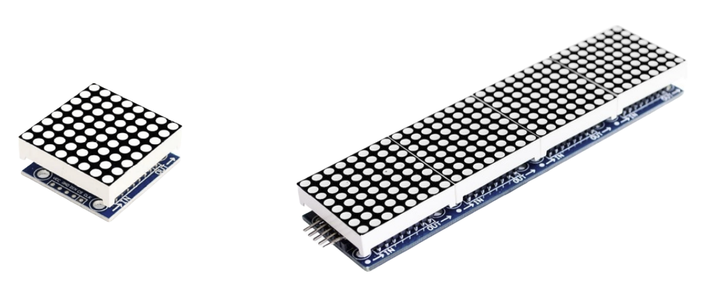
When you connect several 8x8 modules in a row, like an 8x32 display, you get a larger screen that can show longer messages or more detailed images.
The MAX7219 controls all the LEDs in the matrix, handling the complex timing and scanning so you only need to send the data you want to show.
Eight Digit 7-Segment Display
A 7-segment display is made of seven LED segments arranged to form numbers and some letters. The eight-digit version lets you show up to eight characters, making it perfect for clocks, counters, or any project that needs clear numeric output.

Why MAX7219?
No, this section is not about why we chose to write a driver for the MAX7219 chip (we did that because it’s simple and fun). This is about why we need this chip in the first place.
The Problem: Too Many LEDs, Too Few Pins
Imagine you have an 8×8 LED matrix. That's 64 individual LEDs. If you want to control just one LED, it's easy. You connect it to one GPIO pin on the microcontroller and turn it on or off.
But how do you control 64 LEDs with a microcontroller that only has around 20 or 30 GPIOs? You can't give one GPIO for each LED. That would be wasteful. And most microcontrollers don't even have that many pins.
The answer is multiplexing
Multiplexing
Instead of wiring each LED separately, we arrange the 64 LEDs into a grid: 8 rows and 8 columns. Each LED sits at the intersection of a row and a column.
All the cathodes (negative sides) of LEDs in a row are connected together. All the anodes (positive sides) of LEDs in a column are connected together.
Now the question is, how do we light up an LED? Let's say we want to turn on the LED at second row (we'll call it R2) and second column (we'll call it C2).

To turn on the LED at R2 and C2:
-
We set the row line R2 to low (logic 0) to sink current from the cathode
-
We set the column line C2 to high (logic 1) to supply voltage to the anode
This creates a voltage difference across that one LED, and only that LED will turn on. The others will remain off because either their row is not active or their column is not selected.
⚡ NOTE: Some LED matrices work the other way around - with anode lines connected to the rows and cathode lines connected to the columns. I chose to explain it this way because the LED matrix (1088AS) we'll use for testing is arranged like this.
What About Multiple LEDs?
Now suppose we want to light up a diagonal: R1-C1, R2-C2, and R3-C3. If we try to activate all those rows and columns at once, unwanted current paths could cause other LEDs to glow.
Instead, we turn on one row at a time using time-division multiplexing. We start by setting row R1 to low (logic 0) to sink current and set the columns so that only column C1 is high (logic 1) to supply voltage. This lights the LED at R1-C1. Then we set row R1 back to high (turn it off), set row R2 to low, and update the columns so that only column C2 is high. Now the LED at R2-C2 lights up. After that, we do the same for row R3 and column C3. One row at a time.

This is the basic idea of multiplexing. We light up one row at a time, very quickly, and update the columns for that row. Then we move to the next row, and so on. If we repeat this fast enough, our eyes cannot notice the flickering, and it looks like all LEDs are on at the same time. This effect is called persistence of vision. It might sound a bit crazy if you're hearing it for the first time but it works.
The Problem with Doing It in Software
If you try to handle this multiplexing yourself in software, you need to switch rows and columns rapidly, maintain precise timing, and still make time for the rest of your program. It quickly becomes complex and inefficient.
On top of that, you need to connect 8 row pins and 8 column pins, which means using 16 GPIOs. That's a lot of wiring and not practical for most microcontrollers.
The Solution: MAX7219
This is where the MAX7219 comes in.
The MAX7219 is a specialized chip that takes care of all the multiplexing in hardware. You just send the data over SPI, and it does the rest. It automatically cycles through the rows, manages the column states, controls brightness, and refreshes the entire display at high speed. It also stores the current LED states in internal memory, so your microcontroller doesn't have to resend data constantly.
That's why we use the MAX7219. It does the hard part, so we don't have to.
MAX7219 Datasheet:
You can find the datasheet here.
Pin Configuration
The MAX7219 has a total of 24 pins. Out of these, 8 are digit pins (labeled DIG0 to DIG7) and 8 are segment pins (labeled SEG A to SEG G and DP). The remaining pins are used for power and communication.
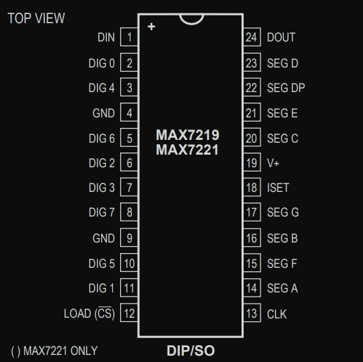
Note: If you read the datasheet, you will also see another chip called MAX7221 mentioned. It is nearly identical to the MAX7219, the main difference is that the MAX7221 supports standard SPI™, QSPI™, and MICROWIRE™ interfaces.
Communication Pins
These four pins are used for serial communication between the microcontroller and the MAX7219:
-
DIN (Data In): We use this pin to send display data to the MAX7219. Whatever we want to show on the LEDs is sent here from the microcontroller.
-
CLK (Clock): This pin provides the clock signal that controls the timing of data transfer.
-
LOAD (Chip Select): Also labeled CS on the MAX7221, this pin tells the chip when to take in the received data and update the display.
-
DOUT (Data Out): If we connect more than one MAX7219 in a chain (called a daisy-chain), this pin passes the data to the next chip. It should be connected to the DIN pin of the next MAX7219 module.
7-Segement Displays
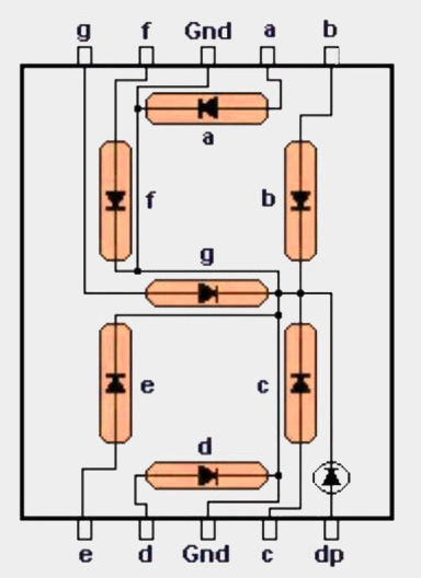
The MAX7219 chip was originally designed to control 7-segment displays. A 7-segment display is basically eight tiny LEDs arranged in the shape of the number "8" - seven for the segments (labeled A to G) and one extra for the decimal point (DP). These segments light up in different combinations to show digits and a few letters.
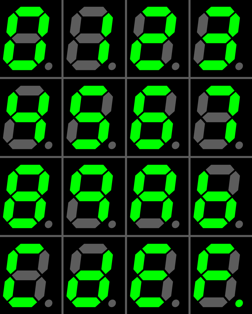
Image credit: Wikimedia
MAX7219 works best with the common cathode type. That just means all the negative ends of the LEDs in one digit are tied together and go to ground. The positive ends (anodes) are controlled separately.

To light up a segment, you just turn on the right anode while the common cathode is active. Want to show the number "1" ? Just turn on segments B and C.
Now let's take a closer look at how the wiring actually works. Like we mentioned earlier, each LED's anode is connected to a dedicated pin. But if you follow the line going to GND, you'll see that all the cathodes are tied together. That's why it's called a common cathode display.
8 Digit 7-Segment Display
That was simple. But let's have a look at how the 8-digit 7-segment display is connected, how the MAX7219 is wired with it, and how it controls the digits.
Now, each digit has its own set of A to G segments and a decimal point. If we had to control all of them directly, that would mean 8 digits * 8 segments = 64 pins! But the MAX7219 only has 24 pins. So how are we going to control all 8 digits with that? You guessed it - multiplexing.
We already talked about how multiplexing works in the intro. It quickly switches between digits one at a time, fast enough that it looks like all the digits are on at the same time.
Here's how it works: all the segment lines (A to G and DP) are shared across all digits. But each digit has its own separate control line. The MAX7219 activates one digit at a time, sets the segment lines to display the right segments for that digit, then moves to the next digit and repeats the process.
So even though only one digit is ON at any given moment, it switches so quickly that our eyes can't tell; it looks like all digits are lit up together.
8-Digit 7-Segment Display Wiring
NOTE: This is wiring of the MAX1499 chip and a 5-digit 7-segment display. This is not the MAX7219, and not an 8-digit display. This diagram is only meant to illustrate the general wiring method. If I have more time, I will create a proper diagram for the MAX7219 and 8-digit display.
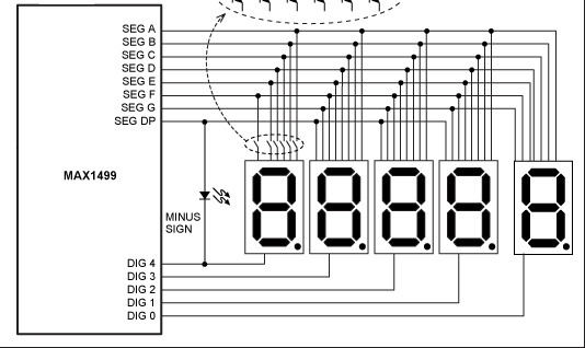
Image credit: Analog.com
As you can see, all the digits share the same segment lines, labeled SEG A to SEG G and SEG DP (Decimal Point). These control which segments light up to form numbers and symbols.
Each digit is activated by its corresponding DIG line. DIG 0 controls the rightmost digit, DIG 1 controls the next one to the left, and so on, up to DIG 4 which controls the leftmost digit.
The chip quickly cycles through these DIG lines one at a time. While one DIG line is active, the SEG lines decide which segments are on.
The same basic idea is used by the MAX7219 to control an 8-digit 7-segment display. But in the case of MAX7219, it supports up to 8 digits, has 8 digit select lines (DIG 0 to DIG 7).
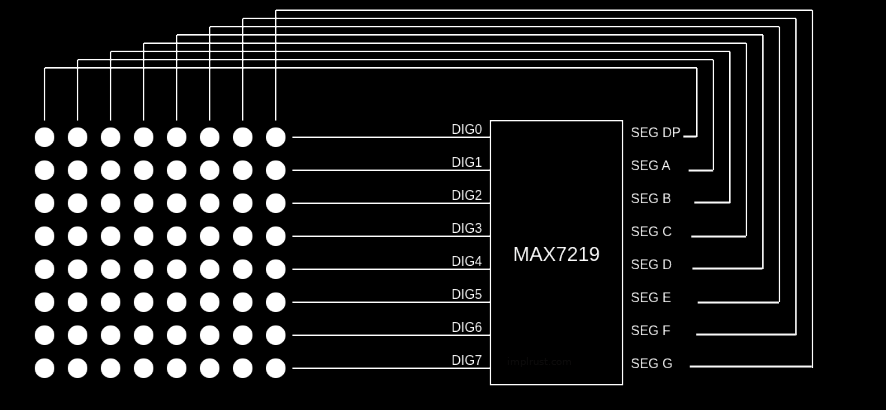
LED Matrix
Now, let's look at the 8x8 LED matrix and how it is arranged and connected to the MAX7219. An 8x8 LED matrix consists of 64 LEDs arranged in rows and columns (8 rows and 8 columns).
The 7-segment display we saw earlier was pretty straightforward and standardized. But unlike that, there is no fixed or universal mapping between the MAX7219's outputs and the rows and columns of the matrix.
Modules
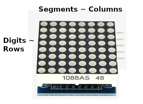
There are different types of LED matrix modules available, and each type may wire the rows and columns differently. This means the display orientation and behavior can vary between modules. Some modules wire them left-to-right, others right-to-left, or even top-to-bottom or bottom-to-top. The two most common types are Generic and FC-16. The FC-16 type is especially popular in daisy-chained matrix displays. I also bought a single matrix FC-16 module for testing.
In this section, I will explain things from the perspective of the FC-16 module. It uses a MAX7219 driver along with a 1088AS LED matrix. According to the 1088AS datasheet, the columns are anodes and the rows are cathodes. This means the MAX7219's segments (which source current) are connected to the columns, while the digits (which sink current) are connected to the rows.
If you are using a single matrix, identifying which side is row and which is column can be confusing because single led matrix is a square. To identify it correctly, position the matrix so that the text "1088AS" is at the bottom and touches the table. When you do that, the input pins for the module will be on the right side(from your point of view).
References
- Assembling FC-16 module: This is the article that i used while soldering and fitting 1088AS LED matrix on the module.
- 1088AS Datasheet
How Do We Tell the MAX7219 What to Show?
To control what the MAX7219 displays, we need to send instructions using the SPI communication. We use the DIN pin to send data, and we synchronize each bit with the CLK pin.
Inside the MAX7219, there are several registers, and each one can store 8 bits of data. These registers helps to control what appears on the display.
To update the display, we send a 16-bit packet. This packet includes two key parts: the register we want to write to and the data we want to store. We send the most significant bit (D15) first, and the least significant bit (D0) last.
Structure of the 16-Bit Data Packet

When we send data to the MAX7219, we send a 16-bit packet. This packet is split into three parts:
-
Bits D8 to D11 (4 bits): This is the register address. It tells the MAX7219 which internal register we want to write to (like a digit register, intensity register, or shutdown register).
-
Bits D0 to D7 (8 bits): This is the data we want to store in that register.
-
Bits D12 to D15 (4 bits): These are "don't care" bits. The MAX7219 ignores them, so we usually just set them to 0
Once all 16 bits are shifted in (using CLK), we toggle the LOAD (or CS) pin high to latch the data into the selected register.
Simplified Register Address Map
The MAX7219 datasheet lists register addresses using a format like 0xXA, 0xXC, etc., where the X represents the upper 4 bits (bits D12-D15) of the 16-bit data packet. These bits are "don't care" because the MAX7219 only uses bits D8-D11 to determine which register to access. The top 4 bits are completely ignored by the chip.
To simplify things, we fill the top nibble with 0 and show only the actual address bits in a standard hexadecimal format. So instead of writing 0xXA, we just use 0x0A. This avoids confusion and clearly shows what you need to send in your SPI packet.
| Address (Hex) | Register Name | Description |
|---|---|---|
0x00 | No-Op | This register performs no operation and is used when cascading multiple MAX7219 chips. |
| Digit Registers | ||
0x01 | Digit 0 | Stores segment data for digit 0 |
0x02 | Digit 1 | Stores segment data for digit 1 |
0x03 | Digit 2 | Stores segment data for digit 2 |
0x04 | Digit 3 | Stores segment data for digit 3 |
0x05 | Digit 4 | Stores segment data for digit 4 |
0x06 | Digit 5 | Stores segment data for digit 5 |
0x07 | Digit 6 | Stores segment data for digit 6 |
0x08 | Digit 7 | Stores segment data for digit 7 |
| Control Registers | ||
0x09 | Decode Mode | Decode Mode: Controls Code B decoding for 7-segment displays, letting the chip automatically map numbers to segments |
0x0A | Intensity | Sets intensity level for the display (0 to 15) |
0x0B | Scan Limit | For 7-segment displays, this controls how many digits (1 to 8) are active. For example, if your display has only 4 digits, setting the limit to 3 (DIG0 to DIG3) can make them brighter because the chip is not spending time driving unused digits. |
0x0C | Shutdown | Turns the display on or off without clearing any data. This is useful for saving power or flashing the display. |
0x0F | Display Test | Lights up all LEDs for testing |
Command to Turn on Display
To turn on the display, we need to send a 16-bit data packet to the MAX7219. The register address 0x0C selects the Shutdown register, and the value 0x01 tells the chip to exit shutdown mode and enable the display. So the complete packet we send is:
#![allow(unused)]
fn main() {
0x0C01
}
This means: "Write the value 0x01 into the Shutdown register." Once this command is sent, the display will turn on and start showing the data stored in the digit registers.
That is it. Our driver will be around how we send 16-bit packets over SPI. Each packet contains the exact data we want to send to the MAX7219 so we can control the display in the way we choose.
Example: Writing to a Digit
Just like we turned the display on by writing to the Shutdown register, we can send data to the digit registers to control what appears. The meaning of the data byte depends on whether we are using a 7-segment display or an 8x8 LED matrix.
7-segment display
In a 7-segment display, the digit registers 0x01 to 0x08 each control one digit. The value you send is a segment code that maps to segments A to G and the decimal point. For example, to show the number 5 on Digit 0 we send:
Note: If the MAX7219's Code B decode mode is enabled (in the Decode Mode register), you can send digit values (0-9) directly to the digit registers. Otherwise, you need to send the segment bit pattern manually.
#![allow(unused)]
fn main() {
[0x01, 0x05]    // 16-bit value 0x0105 represented as a byte array (this is how we actually do it in the code)
}
This means: write the code 0x05 (pattern for 5) into the Digit 0 register.
LED Matrix
In an LED matrix, the digit registers 0x01 to 0x08 represent rows 0 to 7 of the display. The value you send is an 8-bit pattern, where each bit controls one LED in that row. We will use binary to make it clear which LEDs are on.
For example, to turn on the far left and far right LEDs of Row 0 we send:
#![allow(unused)]
fn main() {
[0x01, 0x81]
}
0x81 in binary is:
0x81 = 10000001
Each 1 means the LED at that bit position is on, and each 0 means it is off. In this case, bit 7 and bit 0 are set, so the leftmost and rightmost LEDs in Row 0 are lit.
A typical bit position to column mapping is:
bit 7 -> column 0 (leftmost)
bit 6 -> column 1
bit 5 -> column 2
bit 4 -> column 3
bit 3 -> column 4
bit 2 -> column 5
bit 1 -> column 6
bit 0 -> column 7 (rightmost)
So 10000001 lights columns 0 and 7.
Row 0:  ■  .  .  .  .  .  .  ■
Row 1:  .  .  .  .  .  .  .  .
Row 2:  .  .  .  .  .  .  .  .
Row 3:  .  .  .  .  .  .  .  .
Row 4:  .  .  .  .  .  .  .  .
Row 5:  .  .  .  .  .  .  .  .
Row 6:  .  .  .  .  .  .  .  .
Row 7:  .  .  .  .  .  .  .  .
Create Project
Now that we understand the MAX7219 chip and how data is sent to control the display, we can start building our driver in Rust for a no_std environment.
We will begin by creating a new Rust library crate. The crate will be kept minimal and portable, using only the embedded-hal traits so it can work on any platform that supports them.
Create new library
I named my crate max7219-display, but you can choose any name you like.
#![allow(unused)]
fn main() {
cargo new max7219-display --lib
cd max7219-display
}
Goal
Our goal is to build a minimal driver that can send data to the MAX7219 and provide low-level functions to control the display.
The simplest version could live entirely in lib.rs, but I prefer keeping things organized in separate modules. This makes the code cleaner and easier to scale later.
A final project layout will look like this:
.
├── Cargo.toml
└── src
    ├── driver
    │   ├── max7219.rs
    │   └── mod.rs
    ├── error.rs
    ├── lib.rs
    ├── registers.rs
I've already created a full-featured max7219-display crate and published it on crates.io, with the source code available on GitHub. That version includes extra utilities for working with both LED matrices (single and daisy-chained) and 7-segment displays.
In this guide, we'll focus only on the bare minimum driver. This will give you the core understanding, and if you want, you can later extend it with your own utility functions. I won't cover those extras here so the guide stays focused and uncluttered.
For reference, here's the structure of my full crate:
.
├── Cargo.toml
└── src
    ├── driver
    │   ├── max7219.rs
    │   └── mod.rs
    ├── error.rs
    ├── led_matrix
    │   ├── buffer.rs
    │   ├── display.rs
    │   ├── fonts.rs
    │   ├── mod.rs
    │   ├── scroll.rs
    │   └── symbols.rs
    ├── lib.rs
    ├── registers.rs
    └── seven_segment
        ├── display.rs
        ├── fonts.rs
        └── mod.rs
Creating the Module Structure for Our Driver
We will set up the basic folder and file structure. We are only setting up the structure at this stage. We will add the actual code in the later sections when we start implementing our driver functionality.
Inside the src folder, create the following:
driver/max7219.rs
driver/mod.rs
registers.rs
error.rs
Add the following to driver/mod.rs file:
#![allow(unused)]
fn main() {
mod max7219;
}
Here we have declared the max7219 module as private, meaning it can only be accessed within the driver module.
You might wonder - if it is private, how will we use it outside?
Later, we will create a main struct for our driver called "Max7219" and export only that struct publicly. This approach keeps our internal code hidden and presents a clean public API.
You do not need to strictly follow this approach. If you prefer, you could also make the module public right away by writing pub mod max7219 instead.
In Rust, the lib.rs file is the entry point for a library.
We will declare our modules here:
#![allow(unused)]
fn main() {
pub mod driver;
pub mod error;
pub mod registers;
}
That is all folks! The driver is done! Okay, not really - we just created the structure. We will add the actual code in the next section.
Usual Setup
In this section, we'll go through the basic setup for our library. It's very similar to what we did in the DHT22 chapter. In later chapters, we will skip the explanations for these basic setups and provide only the code.
No Unsafe
If you noticed in the previous chapter, we never used the unsafe keyword in our project. If you want to take it one step further and make sure no unsafe code can ever slip into your driver, you can enforce it with this flag at the top of your crate:
#![allow(unused)]
#![deny(unsafe_code)]
fn main() {
}
Mark the Crate as no_std
To make our library compatible with embedded systems that don't have access to the standard library, we need to mark it as no_std.
Open the src/lib.rs file, remove all lines and add the following line at the very top:
#![allow(unused)]
#![cfg_attr(not(test), no_std)]
fn main() {
}
This tells the Rust compiler to avoid linking the standard library when we are not running tests. Instead, the crate will rely only on the core crate, which provides essential Rust features like basic types and operations. As a result, we won't be able to use any features from the std crate - only what's available in core.
The cfg_attr is a conditional attribute. It means "if not testing, then apply no_std." This way, we can still write normal unit tests using std, but the compiled library will work in no_std environments.
Add Dependencies
Next, open Cargo.toml and add the embedded-hal crate under [dependencies]. This allows your driver to work with any compatible GPIO or delay implementation:
[dependencies]
embedded-hal = "1.0.0"
Dev dependencies
This time, we add the embedded-hal-mock crate now itself under dev-dependencies, since we are already familiar with it. This lets us write tests by simulating embedded-hal traits:
[dev-dependencies]
embedded-hal-mock = { version = "0.11.1", features = ["eh1"] }
Error Handling
In this chapter, we will explain how error handling is designed and implemented in our MAX7219 driver using Rust's enum and traits. All these related code goes inside the error.rs module.
During interaction with this chip, many things can fail:
-
The user might configure an invalid number of devices.
-
The driver might receive invalid commands or indices.
-
SPI communication can fail due to hardware issues.
Defining the Error Enum
We define a custom Error enum that lists all the possible errors the driver can produce:
#![allow(unused)]
fn main() {
#[derive(Debug, PartialEq, Eq)]
pub enum Error {
    /// The specified device count is invalid (exceeds maximum allowed).
    InvalidDeviceCount,
    /// Invalid scan limit value (must be 0-7)
    InvalidScanLimit,
    /// The specified register address is not valid for the MAX7219.
    InvalidRegister,
    /// Invalid device index (exceeds configured number of devices)
    InvalidDeviceIndex,
    /// Invalid digit position (0-7 for MAX7219)
    InvalidDigit,
    /// Invalid intensity value (must be 0-15)
    InvalidIntensity,
    /// SPI communication error
    SpiError,
}
}
Converting SPI Errors into Our Driver Error
The MAX7219 driver communicates over SPI, which may produce errors defined by the SPI implementation. To unify error handling, we implement From
#![allow(unused)]
fn main() {
impl<E> From<E> for Error
where
    E: embedded_hal::spi::Error,
{
    fn from(_value: E) -> Self {
        Self::SpiError
    }
}
}
This lets us use the ? operator with SPI calls inside the driver, automatically converting any SPI-specific error into the driver's SpiError variant. It simplifies error propagation and keeps our API consistent.
Implementing Display for User-Friendly Messages
To make errors easier to read and understand, we implement the Display trait for our Error enum. This allows errors to be formatted as human-friendly strings, useful for logging or debugging:
#![allow(unused)]
fn main() {
impl core::fmt::Display for Error {
    fn fmt(&self, f: &mut core::fmt::Formatter<'_>) -> core::fmt::Result {
        match self {
            Self::SpiError => write!(f, "SPI communication error"),
            Self::InvalidDeviceIndex => write!(f, "Invalid device index"),
            Self::InvalidDigit => write!(f, "Invalid digit"),
            Self::InvalidIntensity => write!(f, "Invalid intensity value"),
            Self::InvalidScanLimit => write!(f, "Invalid scan limit value"),
            Self::InvalidDeviceCount => write!(f, "Invalid device count"),
            Self::InvalidRegister => write!(f, "Invalid register address"),
        }
    }
}
}
Update lib.rs
To simplify function signatures throughout the driver, we define a crate-local Result type alias that defaults the error type to our custom Error:
#![allow(unused)]
fn main() {
pub(crate) type Result<T> = core::result::Result<T, crate::error::Error>;
}
This lets us write all function signatures using just Result
Instead of writing:
#![allow(unused)]
fn main() {
fn set_intensity(intensity: u8) -> core::result::Result<(), crate::error::Error> {
    //..
}
}
we can simply write:
#![allow(unused)]
fn main() {
fn set_intensity(intensity: u8) -> Result<()> {
    // ...
}
}
Test Code for Error Handling
Nothing much happening in this test. We're not even using embedded-hal-mock crate here. Just normal test code. You can paste this at the bottom of the error.rs module.
#![allow(unused)]
fn main() {
#[cfg(test)]
mod tests {
    use super::*;

    // Mock SPI error for testing
    #[derive(Debug)]
    struct MockSpiError;

    impl core::fmt::Display for MockSpiError {
        fn fmt(&self, f: &mut core::fmt::Formatter<'_>) -> core::fmt::Result {
            write!(f, "Mock SPI error")
        }
    }

    impl embedded_hal::spi::Error for MockSpiError {
        fn kind(&self) -> embedded_hal::spi::ErrorKind {
            embedded_hal::spi::ErrorKind::Other
        }
    }

    #[test]
    fn test_error_device() {
        assert_eq!(
            format!("{}", Error::InvalidDeviceCount),
            "Invalid device count"
        );
        assert_eq!(
            format!("{}", Error::InvalidScanLimit),
            "Invalid scan limit value"
        );
        assert_eq!(
            format!("{}", Error::InvalidRegister),
            "Invalid register address"
        );
        assert_eq!(
            format!("{}", Error::InvalidDeviceIndex),
            "Invalid device index"
        );
        assert_eq!(format!("{}", Error::InvalidDigit), "Invalid digit");
        assert_eq!(
            format!("{}", Error::InvalidIntensity),
            "Invalid intensity value"
        );
        assert_eq!(format!("{}", Error::SpiError), "SPI communication error");
    }

    #[test]
    fn test_error_debug() {
        // Test that Debug trait is implemented and works
        let error = Error::InvalidDigit;
        let debug_output = format!("{error:?}",);
        assert!(debug_output.contains("InvalidDigit"));
    }

    #[test]
    fn test_from_spi_error() {
        let spi_error = MockSpiError;
        let error = Error::from(spi_error);
        assert_eq!(error, Error::SpiError);
    }

    #[test]
    fn test_error_partialeq() {
        // Test that all variants implement PartialEq correctly
        assert!(Error::InvalidDeviceCount.eq(&Error::InvalidDeviceCount));
        assert!(!Error::InvalidDeviceCount.eq(&Error::InvalidScanLimit));
    }
}
}
Registers Module
In this chapter, we will work on the registers module(registers.rs). We could use the register values directly, but using enums is more idiomatic and provides better type safety. We will define two enums here: Register and DecodeMode.
The Register enum holds the addresses of each digit register and control register values, which we saw in the data transfer section. The DecodeMode enum is for configuring automatic digit decoding on seven-segment displays. For LED matrix displays, it should be set to NoDecode.
Add the neceessary imports for the module:
#![allow(unused)]
fn main() {
use crate::{Result, error::Error};
}
The Register Enum
In this enum, we declare all the MAX7219 registers, with each name matching its register address. To make working with these registers easier, we also implement some basic traits that let us copy and compare the register values.
#![allow(unused)]
fn main() {
#[derive(Debug, Clone, Copy, PartialEq, Eq)]
#[repr(u8)]
pub enum Register {
    /// No-op register
    NoOp = 0x00,
    /// Digit 0 register
    Digit0 = 0x01,
    /// Digit 1 register
    Digit1 = 0x02,
    /// Digit 2 register
    Digit2 = 0x03,
    /// Digit 3 register
    Digit3 = 0x04,
    /// Digit 4 register
    Digit4 = 0x05,
    /// Digit 5 register
    Digit5 = 0x06,
    /// Digit 6 register
    Digit6 = 0x07,
    /// Digit 7 register
    Digit7 = 0x08,
    /// Decode mode register
    DecodeMode = 0x09,
    /// Intensity register
    Intensity = 0x0A,
    /// Scan limit register
    ScanLimit = 0x0B,
    /// Shutdown register
    Shutdown = 0x0C,
    /// Display test register
    DisplayTest = 0x0F,
}
}
Next, we will add some functions that will be helpful later.
First, we will add the addr method that converts a register into its raw u8 value. This is useful when we need to send the register address to the MAX7219 chip.
Next, we will add try_digit function that takes a number and tries to convert it into the matching digit register (Digit0 to Digit7). If the number is out of range, it returns an invalid digit error. If you are wondering why I didn't implement the TryFrom trait, it is because I want to accept only digit registers. Later in the code, when the user sends a digit as input, we need a function to check if it is a valid digit. By the way, this is an internal function we will use only inside the crate to validate user input. So, we mark it with pub(crate).
We also declare another helper function that gives us an iterator. This returns all the digit registers. This is useful when you want to loop through all digits - for example, to update every row or column on the display.
#![allow(unused)]

fn main() {
impl Register {
    /// Convert register to u8 value
    pub const fn addr(self) -> u8 {
        self as u8
    }

    /// Try to convert a digit index (0-7) into a corresponding `Register::DigitN`.
    pub(crate) fn try_digit(digit: u8) -> Result<Self> {
        match digit {
            0 => Ok(Register::Digit0),
            1 => Ok(Register::Digit1),
            2 => Ok(Register::Digit2),
            3 => Ok(Register::Digit3),
            4 => Ok(Register::Digit4),
            5 => Ok(Register::Digit5),
            6 => Ok(Register::Digit6),
            7 => Ok(Register::Digit7),
            _ => Err(Error::InvalidDigit),
        }
    }

    /// Returns an iterator over all digit registers (Digit0 to Digit7).
    ///
    /// Useful for iterating through display rows or columns when writing
    /// to all digits of a MAX7219 device in order.
    pub fn digits() -> impl Iterator<Item = Register> {
        [
            Register::Digit0,
            Register::Digit1,
            Register::Digit2,
            Register::Digit3,
            Register::Digit4,
            Register::Digit5,
            Register::Digit6,
            Register::Digit7,
        ]
        .into_iter()
    }
}
}
The DecodeMode Enum
This enum defines how the MAX7219 decodes the values you send to it for each digit.
The MAX7219 can do something called Code B decoding. When enabled, it automatically converts numbers and few letters (like 0-9, E, H, L, and some others) into the correct 7-segment patterns. This means you don't have to manually control each LED segment yourself.
The DecodeMode enum lets you choose which digits use this automatic decoding and which digits you want to control manually with raw segment data.
-
NoDecode means all digits are manual; you control every segment yourself. This is the settings normally used with LED Matrix Displays.
-
Digit0 enables decoding only for the first digit.
-
Digits0To3 enables decoding for digits 0 to 3; often used for 4-digit 7-segment displays.
-
AllDigits turns on decoding for all eight digits.
#![allow(unused)]
fn main() {
/// Decode mode configuration for the MAX7219 display driver.
///
/// Code B decoding allows the driver to automatically convert certain values
/// (such as 0-9, E, H, L, and others) into their corresponding 7-segment patterns.
/// Digits not using Code B must be controlled manually using raw segment data.
///
/// Use this to configure which digits should use Code B decoding and which
/// should remain in raw segment mode.
#[derive(Debug, Clone, Copy, PartialEq, Eq)]
#[repr(u8)]
pub enum DecodeMode {
    /// Disable Code B decoding for all digits (DIG0 to DIG7).
    ///
    /// In this mode, you must manually set each segment (A to G and DP)
    /// using raw segment data.
    NoDecode = 0x00,

    /// Enable Code B decoding for only digit 0 (DIG0).
    ///
    /// All other digits (DIG1 to DIG7) must be controlled manually.
    Digit0 = 0x01,

    /// Enable Code B decoding for digits 0 through 3 (DIG0 to DIG3).
    ///
    /// This is commonly used for 4-digit numeric displays.
    Digits0To3 = 0x0F,

    /// Enable Code B decoding for all digits (DIG0 to DIG7).
    ///
    /// This is typically used for full 8-digit numeric displays.
    AllDigits = 0xFF,
}
}
We also add a simple method value() that converts the enum into the number you need to send to the MAX7219 decode mode register.
#![allow(unused)]
fn main() {
impl DecodeMode {
    /// Convert decode mode to u8 value
    pub const fn value(self) -> u8 {
        self as u8
    }
}
}
Tests for Register Module
These are simple tests to verify the basic functionality of the Register and DecodeMode enums. Place them at the bottom of the registers.rs module.
#![allow(unused)]

fn main() {
#[cfg(test)]
mod tests {
    use super::*;

    #[test]
    fn test_register_addr() {
        assert_eq!(Register::NoOp.addr(), 0x00);
        assert_eq!(Register::Digit0.addr(), 0x01);
        assert_eq!(Register::Digit7.addr(), 0x08);
        assert_eq!(Register::DecodeMode.addr(), 0x09);
        assert_eq!(Register::Intensity.addr(), 0x0A);
        assert_eq!(Register::ScanLimit.addr(), 0x0B);
        assert_eq!(Register::Shutdown.addr(), 0x0C);
        assert_eq!(Register::DisplayTest.addr(), 0x0F);
    }

    #[test]
    fn test_digits_iterator() {
        let expected = [
            Register::Digit0,
            Register::Digit1,
            Register::Digit2,
            Register::Digit3,
            Register::Digit4,
            Register::Digit5,
            Register::Digit6,
            Register::Digit7,
        ];
        let actual: Vec<Register> = Register::digits().collect();
        assert_eq!(actual, expected);
    }

    #[test]
    fn test_decode_mode_value() {
        assert_eq!(DecodeMode::NoDecode.value(), 0x00);
        assert_eq!(DecodeMode::Digit0.value(), 0x01);
        assert_eq!(DecodeMode::Digits0To3.value(), 0x0F);
        assert_eq!(DecodeMode::AllDigits.value(), 0xFF);
    }
}
}
Write an Embedded Rust Driver for the MAX7219
Now, we will start working on the core functionalities of the MAX7219 driver. We will create a struct called Max7219. This struct will be exposed to the user so they can use it to control the MAX7219 chip.
Before getting into that, let's declare two constants in the main lib module (lib.rs file). We need these for our Max7219 struct:
#![allow(unused)]
fn main() {
/// Maximum number of daisy-chained displays supported
pub const MAX_DISPLAYS: usize = 8;

/// Number of digits (0 to 7) controlled by one MAX7219
pub const NUM_DIGITS: u8 = 8;
}
After this, we re-export the Max7219 struct so users can access it:
Note: At this point, you will get a compiler error because we haven't defined the Max7219 struct yet. Don't worry, we will create it in the next steps.
#![allow(unused)]
fn main() {
pub use max7219::Max7219;
}
From now on, we will be working on the max7219 module (driver/max7219.rs file).
Imports
To start, we import the SpiDevice trait from embedded-hal since our driver will communicate over SPI. We also bring in constants like MAX_DISPLAYS and NUM_DIGITS, our custom Result type, the Error enum for error handling, and the DecodeMode and Register enums from the registers module.
#![allow(unused)]
fn main() {
use embedded_hal::spi::SpiDevice;

use crate::{
    MAX_DISPLAYS, NUM_DIGITS, Result,
    error::Error,
    registers::{DecodeMode, Register},
};
}
Max7219 struct
Let's start with defining the main struct. This struct will hold the generic SPI interface, a buffer for preparing data, and the count of devices connected in a daisy chain.
#![allow(unused)]
fn main() {
/// Driver for the MAX7219 LED display controller.
/// Communicates over SPI using the embedded-hal `SpiDevice` trait.
pub struct Max7219<SPI> {
    spi: SPI,
    buffer: [u8; MAX_DISPLAYS * 2],
    device_count: usize,
}
}
The struct is generic over the SPI type because we want it to work with any SPI device that implements the embedded-hal SpiDevice trait. This makes our driver flexible and compatible with many hardware platforms.
The buffer is a fixed-size array used to build the full SPI data packet for all connected devices. Each MAX7219 device expects a 16-bit packet: 1 byte for the register address and 1 byte for the data. When multiple devices are chained together, we send data for all devices. The buffer size is MAX_DISPLAYS * 2 because we reserve space for the maximum number of devices.
The device_count keeps track of how many MAX7219 devices are connected in the chain. This is important because we only fill and send data for the connected devices, not the full maximum buffer.
Initialization functions
In this section, we define functions that the end user will use to create and initialize new instances of the Max7219 struct. These functions provide the starting point for using the driver. Later, we will add other methods for the struct inside the same implementation block.
From here on, all functions should be placed inside this block:
#![allow(unused)]
fn main() {
impl<SPI> Max7219<SPI>
where
    SPI: SpiDevice,
{
    // Initialization and other methods go here
}
}
Creating a new driver instance
This function creates a new Max7219 driver using the given SPI interface. It defaults to controlling a single device. You can use with_device_count method later to specify more devices in a chain.
The SPI must use Mode 0 (clock low when idle, data read on the rising clock edge) and run at 10 MHz or less as required by the MAX7219 datasheet. We leave it to the user to make sure these settings are correct.
#![allow(unused)]
fn main() {
pub fn new(spi: SPI) -> Self {
    Self {
        spi,
        device_count: 1, // Default to 1, use with_device_count to increase count
        buffer: [0; MAX_DISPLAYS * 2],
    }
}
}
Setting the number of devices
This method lets you set how many daisy-chained MAX7219 devices you want to control. If you try to set a number larger than the maximum allowed (MAX_DISPLAYS), it returns an error. For example, with LED matrices, you might have a single matrix, or 4 or 8 matrices chained together. This method lets you tell the driver how many are connected.
#![allow(unused)]
fn main() {
 pub fn with_device_count(mut self, count: usize) -> Result<Self> {
    if count > MAX_DISPLAYS {
        return Err(Error::InvalidDeviceCount);
    }
    self.device_count = count;
    Ok(self)
}
}
Device Count Helper Function
We also create this function to let the user check how many MAX7219 devices are currently connected in the chain. It simply returns the device count stored inside the driver.
#![allow(unused)]
fn main() {
pub fn device_count(&self) -> usize {
    self.device_count
}
}
Initialization from the User's Perspective
There is one more function we need to define called init() that will do basic setup for the MAX7219 and get it ready to use. I originally thought to include it in this section, but since it depends on other functions, we will add it later.
From the end user's perspective, they will create an instance of our driver and then initialize it like this:
#![allow(unused)]
fn main() {
// Example
let driver = Max7219::new(spi_dev).with_device_count(4).unwrap();
driver.init().unwrap(); // we will define this later
}
Tests
We will write simple tests to verify the basic behavior of the new and with_device_count functions. First, we check the default device count is 1. Next, we confirm setting a valid device count works correctly. Finally, we verify setting an invalid count returns the expected error. We will place these tests at the bottom of the max7219.rs module. Any other test functions we create later for the max7219 module should be placed inside the same mod tests block.
We use Spi Mock from embedded_hal_mock to simulate the SPI interface, ensuring our driver works correctly with the SpiDevice trait.
#![allow(unused)]

fn main() {
#[cfg(test)]
mod tests {
    use super::*;
    use crate::MAX_DISPLAYS;
    use embedded_hal_mock::eh1::spi::Mock as SpiMock;

    #[test]
    fn test_new() {
        let mut spi = SpiMock::new(&[]);
        let driver = Max7219::new(&mut spi);
        // Default device count => 1
        assert_eq!(driver.device_count(), 1);

        spi.done();
    }

    #[test]
    fn test_with_device_count_valid() {
        let mut spi = SpiMock::new(&[]);
        let driver = Max7219::new(&mut spi);
        let driver = driver
            .with_device_count(4)
            .expect("Should accept valid count");
        assert_eq!(driver.device_count(), 4);
        spi.done();
    }

    #[test]
    fn test_with_device_count_invalid() {
        let mut spi = SpiMock::new(&[]);
        let driver = Max7219::new(&mut spi);
        let result = driver.with_device_count(MAX_DISPLAYS + 1);
        assert!(matches!(result, Err(Error::InvalidDeviceCount)));

        spi.done();
    }
}
}
SPI Communication
We will write two internal helper functions to handle SPI communication with the MAX7219 devices in the chain(or just single device).
Writing to a Single Device Register in the Chain
The first function, write_device_register, sends a single register update to one device in the chain. We start by clearing the entire buffer and then fill only the 2-byte packet (register address and data) for the target device at the correct position in the buffer. Finally, we send the buffer up to the length needed for the connected devices.
If there is just a single device (device index 0, which is the closest to the microcontroller), the offset for the register address is 0 * 2 = 0, and the data byte goes to index 1.
When there are multiple devices, we write at the right offset for the target device, and the rest of the buffer remains zeros (no-ops) to avoid affecting other devices.
For example, if there are 4 devices and we want to write to the device at index 2 (the third device from the left), the offset for the register address is 2 * 2 = 4, and the data byte goes at index 5.
So the full data sent through SPI will look like this (2 bytes per device):
| Index | 0 | 1 | 2 | 3 | 4 | 5 | 6 | 7 |
|---|---|---|---|---|---|---|---|---|
| Value | 0 | 0 | 0 | 0 | register_addr | data | 0 | 0 |
#![allow(unused)]
fn main() {
pub(crate) fn write_device_register(
    &mut self,
    device_index: usize,
    register: Register,
    data: u8,
) -> Result<()> {
    if device_index >= self.device_count {
        return Err(Error::InvalidDeviceIndex);
    }

    self.buffer = [0; MAX_DISPLAYS * 2];

    let offset = device_index * 2; // 2 bytes(16 bits packet) per display
    self.buffer[offset] = register as u8;
    self.buffer[offset + 1] = data;

    self.spi.write(&self.buffer[0..self.device_count * 2])?;

    Ok(())
}
}
Writing to All Device Registers at Once
We will create a second function called write_all_registers that allows us to send register updates to every device in the daisy chain in a single SPI transaction. This approach is more efficient for operations such as powering on all devices, adjusting brightness, or applying other settings to all displays at once.
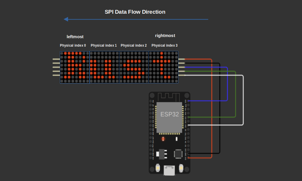
It takes a slice of (Register, u8) tuples, where each tuple contains the register and data for each device in the chain.
We start by clearing the buffer. Then we start filling packets for each devices. The packet we write in the first index of the array goes to leftmost device.
In a daisy chain, the MAX7219 shifts data starting from the rightmost device, which is closest to the microcontroller, toward the leftmost device. So when SPI sends data starting at index 0 in the buffer, that packet actually ends up at the leftmost device.
For example, if we have 4 devices and want to send register-data pairs to all, the buffer fills like this:
| Index | 0 | 1 | 2 | 3 | 4 | 5 | 6 | 7 |
|---|---|---|---|---|---|---|---|---|
| Content | reg_0 | data_0 | reg_1 | data_1 | reg_2 | data_2 | reg_3 | data_3 |
Here, bytes 0 and 1 are for device 0, bytes 2 and 3 for device 1, and so on.
#![allow(unused)]
fn main() {
pub(crate) fn write_all_registers(&mut self, ops: &[(Register, u8)]) -> Result<()> {
    // clear the buffer: 2 bytes per device
    self.buffer = [0; MAX_DISPLAYS * 2];

    // fill in reverse order so that SPI shifts into the last device first
    for (i, &(reg, data)) in ops.iter().enumerate() {
        let offset = i * 2;
        self.buffer[offset] = reg as u8;
        self.buffer[offset + 1] = data;
    }

    // send exactly device_count packets
    let len = self.device_count * 2;
    self.spi.write(&self.buffer[..len])?;

    Ok(())
}
}
If you are curious and want to understand it better, you can remove the pub(crate) marker from these functions to make them accessible outside the crate. Then, create an instance of the Max7219 struct and call these functions with raw register values. For example, try sending 0x01 to the Shutdown register and watch how the display reacts. (At least that's what I did when I was building the driver and testing the initial setup.)
Tests
We add tests to verify the SPI communication functions. One test checks that writing to a device index outside the allowed range returns an error. Another test confirms that writing to a valid device index sends the correct SPI data for that device while sending no-ops to others. The third test verifies that write_all_registers sends the correct data for all devices in the chain in one SPI transaction.
As you might already know (we explained this in the DHT22 driver chapter), when using the embedded-hal mock, we need to set expectations; in this case, for the SPI mock. Each SPI transaction must be marked clearly using the transaction_start and transaction_end functions.
If you look at the test_write_all_registers_valid function, you'll see that all the SPI data is wrapped inside a single transaction. This is because the write_all_registers function uses just one SPI transaction to send commands to all devices at once.
#![allow(unused)]
fn main() {
#[cfg(test)]
mod tests { // The same block as we created before
    // Update the imports:
    use super::*;
    use crate::MAX_DISPLAYS;
    use embedded_hal_mock::eh1::{spi::Mock as SpiMock, spi::Transaction}; // just imported Transaction

    #[test]
    fn test_write_device_register_valid_index() {
        let expected_transactions = [
            Transaction::transaction_start(),
            Transaction::write_vec(vec![
                Register::Shutdown.addr(),
                0x01,
                0x00, // no-op for second device in chain
                0x00,
            ]),
            Transaction::transaction_end(),
        ];
        let mut spi = SpiMock::new(&expected_transactions);
        let mut driver = Max7219::new(&mut spi)
            .with_device_count(2)
            .expect("Should accept valid count");

        driver
            .write_device_register(0, Register::Shutdown, 0x01)
            .expect("should write register");

        spi.done();
    }

    #[test]
    fn test_write_device_register_invalid_index() {
        let mut spi = SpiMock::new(&[]); // No SPI transactions expected
        let mut driver = Max7219::new(&mut spi)
            .with_device_count(2)
            .expect("Should accept valid count");

        let result = driver.write_device_register(2, Register::Shutdown, 0x01); // Index 2 is invalid for device_count=2
        assert_eq!(result, Err(Error::InvalidDeviceIndex));

        spi.done();
    }

    #[test]
    fn test_write_all_registers_valid() {
        let expected_transactions = [
            Transaction::transaction_start(),
            Transaction::write_vec(vec![
                Register::Intensity.addr(),
                0x01,
                Register::Intensity.addr(),
                0x01,
            ]),
            Transaction::transaction_end(),
        ];
        let mut spi = SpiMock::new(&expected_transactions);
        let mut driver = Max7219::new(&mut spi)
            .with_device_count(2)
            .expect("Should accept valid count");

        driver
            .write_all_registers(&[(Register::Intensity, 0x01), (Register::Intensity, 0x01)])
            .expect("should  write all registers");

        spi.done();
    }
}
}
Basic control
Now, we are going to define functions that use our low-level SPI methods to control the MAX7219 chip by writing the right values to specific registers. They make it easy to perform common tasks like turning devices on or off, testing the display, clearing it, or setting limits and brightness.
Power On and Power Off All Devices
These functions let us power on or power off all the MAX7219 devices in the daisy chain at once. They use the write_all_registers function to send the Shutdown command to every device simultaneously.
#![allow(unused)]
fn main() {
pub fn power_on(&mut self) -> Result<()> {
    let ops = [(Register::Shutdown, 0x01); MAX_DISPLAYS];

    self.write_all_registers(&ops[..self.device_count])
}
pub fn power_off(&mut self) -> Result<()> {
    let ops = [(Register::Shutdown, 0x00); MAX_DISPLAYS];

    self.write_all_registers(&ops[..self.device_count])
}
}
Power On and Power Off a Single Device
These functions target just one device in the chain, turning it on or off by writing the Shutdown register for that device only.
#![allow(unused)]
fn main() {
pub fn power_on_device(&mut self, device_index: usize) -> Result<()> {
    self.write_device_register(device_index, Register::Shutdown, 0x01)
}

pub fn power_off_device(&mut self, device_index: usize) -> Result<()> {
    self.write_device_register(device_index, Register::Shutdown, 0x00)
}
}
Enable or Disable Display Test Mode
These allow you to enable or disable the test mode that lights up all segments of the display. You can test one device or all devices at once.
#![allow(unused)]
fn main() {
pub fn test_device(&mut self, device_index: usize, enable: bool) -> Result<()> {
        let data = if enable { 0x01 } else { 0x00 };
        self.write_device_register(device_index, Register::DisplayTest, data)
}

pub fn test_all(&mut self, enable: bool) -> Result<()> {
    let data = if enable { 0x01 } else { 0x00 };
    let ops: [(Register, u8); MAX_DISPLAYS] = [(Register::DisplayTest, data); MAX_DISPLAYS];
    self.write_all_registers(&ops[..self.device_count])
}
}
Clear the Display
These functions clear the display by writing zero to all digit registers. You can clear a single device or all devices.
#![allow(unused)]
fn main() {
pub fn clear_display(&mut self, device_index: usize) -> Result<()> {
    for digit_register in Register::digits() {
        self.write_device_register(device_index, digit_register, 0x00)?;
    }
    Ok(())
}

pub fn clear_all(&mut self) -> Result<()> {
    for digit_register in Register::digits() {
        let ops = [(digit_register, 0x00); MAX_DISPLAYS];
        self.write_all_registers(&ops[..self.device_count])?;
    }

    Ok(())
}
}
Set Intensity (Brightness)
You can control the brightness of a single device or all devices using these functions. Valid intensity values are from 0 to 15 (0x0F). Values outside this range return an error.
#![allow(unused)]
fn main() {
pub fn set_intensity(&mut self, device_index: usize, intensity: u8) -> Result<()> {
    if intensity > 0x0F {
        return Err(Error::InvalidIntensity);
    }
    self.write_device_register(device_index, Register::Intensity, intensity)
}

pub fn set_intensity_all(&mut self, intensity: u8) -> Result<()> {
    if intensity > 0x0F {
        return Err(Error::InvalidIntensity);
    }
    let ops = [(Register::Intensity, intensity); MAX_DISPLAYS];
    self.write_all_registers(&ops[..self.device_count])
}
}
Set Scan Limit (Digits Visible)
The scan limit controls how many digits the display will show (from 1 to 8). These functions set the scan limit for a single device or all devices. The driver validates the input and returns an error if it’s out of range. This is mainly for the 7-segment display.
#![allow(unused)]
fn main() {
pub fn set_device_scan_limit(&mut self, device_index: usize, limit: u8) -> Result<()> {
    if !(1..=8).contains(&limit) {
        return Err(Error::InvalidScanLimit);
    }

    self.write_device_register(device_index, Register::ScanLimit, limit - 1)
}

pub fn set_scan_limit_all(&mut self, limit: u8) -> Result<()> {
    if !(1..=8).contains(&limit) {
        return Err(Error::InvalidScanLimit);
    }
    let val = limit - 1;
    let ops: [(Register, u8); MAX_DISPLAYS] = [(Register::ScanLimit, val); MAX_DISPLAYS];
    self.write_all_registers(&ops[..self.device_count])
}

}
Tests
We will add tests to make sure the basic control functions work correctly and send the right SPI commands. These tests check turning power on and off for all devices or just one device, handling invalid device indexes, enabling and disabling test mode, setting scan limits and brightness (intensity) with proper input validation, and clearing the display.
Each test uses the embedded-hal mock SPI and sets expectations for SPI transactions, including marking the start and end of each transaction and verifying the exact bytes sent.
#![allow(unused)]
fn main() {
#[test]
fn test_power_on() {
    let expected_transactions = [
        Transaction::transaction_start(),
        Transaction::write_vec(vec![Register::Shutdown.addr(), 0x01]),
        Transaction::transaction_end(),
    ];
    let mut spi = SpiMock::new(&expected_transactions);
    let mut driver = Max7219::new(&mut spi);

    driver.power_on().expect("Power on should succeed");
    spi.done();
}

#[test]
fn test_power_off() {
    let expected_transactions = [
        Transaction::transaction_start(),
        Transaction::write_vec(vec![Register::Shutdown.addr(), 0x00]),
        Transaction::transaction_end(),
    ];
    let mut spi = SpiMock::new(&expected_transactions);
    let mut driver = Max7219::new(&mut spi);

    driver.power_off().expect("Power off should succeed");
    spi.done();
}

#[test]
fn test_power_on_device() {
    let expected_transactions = [
        Transaction::transaction_start(),
        Transaction::write_vec(vec![Register::Shutdown.addr(), 0x01]),
        Transaction::transaction_end(),
    ];
    let mut spi = SpiMock::new(&expected_transactions);
    let mut driver = Max7219::new(&mut spi);

    driver
        .power_on_device(0)
        .expect("Power on display should succeed");
    spi.done();
}

// Test with multiple devices - power_on
#[test]
fn test_power_on_multiple_devices() {
    let device_count = 3;

    let expected_transactions = [
        Transaction::transaction_start(),
        Transaction::write_vec(vec![
            Register::Shutdown.addr(),
            0x01,
            Register::Shutdown.addr(),
            0x01,
            Register::Shutdown.addr(),
            0x01,
        ]),
        Transaction::transaction_end(),
    ];
    let mut spi = SpiMock::new(&expected_transactions);
    let mut driver = Max7219::new(&mut spi)
        .with_device_count(device_count)
        .expect("Should accept valid count");

    driver.power_on().expect("Power on should succeed");
    spi.done();
}

#[test]
fn test_power_off_device() {
    let expected_transactions = [
        Transaction::transaction_start(),
        Transaction::write_vec(vec![
            // For 4 devices
            Register::NoOp.addr(),
            0x00,
            Register::NoOp.addr(),
            0x00,
            Register::Shutdown.addr(),
            0x00,
            Register::NoOp.addr(),
            0x00,
        ]),
        Transaction::transaction_end(),
    ];
    let mut spi = SpiMock::new(&expected_transactions);
    let mut driver = Max7219::new(&mut spi)
        .with_device_count(4)
        .expect("a valid device count");

    driver
        .power_off_device(2)
        .expect("Power off display should succeed");
    spi.done();
}

#[test]
fn test_power_device_invalid_index() {
    let mut spi = SpiMock::new(&[]);
    let mut driver = Max7219::new(&mut spi).with_device_count(1).unwrap();

    let result = driver.power_on_device(1);
    assert_eq!(result, Err(Error::InvalidDeviceIndex));

    let result = driver.power_off_device(1);
    assert_eq!(result, Err(Error::InvalidDeviceIndex));
    spi.done();
}

#[test]
fn test_test_all_enable() {
    let expected_transactions = [
        Transaction::transaction_start(),
        Transaction::write_vec(vec![
            Register::DisplayTest.addr(),
            0x01,
            Register::DisplayTest.addr(),
            0x01,
            Register::DisplayTest.addr(),
            0x01,
            Register::DisplayTest.addr(),
            0x01,
        ]),
        Transaction::transaction_end(),
    ];
    let mut spi = SpiMock::new(&expected_transactions);
    let mut driver = Max7219::new(&mut spi)
        .with_device_count(4)
        .expect("valid device count");

    driver
        .test_all(true)
        .expect("Test all enable should succeed");
    spi.done();
}

#[test]
fn test_test_all_disable() {
    let expected_transactions = [
        Transaction::transaction_start(),
        Transaction::write_vec(vec![Register::DisplayTest.addr(), 0x00]),
        Transaction::transaction_end(),
    ];
    let mut spi = SpiMock::new(&expected_transactions);
    let mut driver = Max7219::new(&mut spi);

    driver
        .test_all(false)
        .expect("Test all disable should succeed");
    spi.done();
}

#[test]
fn test_set_scan_limit_all_valid() {
    let limit = 4;
    let expected_transactions = [
        Transaction::transaction_start(),
        Transaction::write_vec(vec![Register::ScanLimit.addr(), limit - 1]),
        Transaction::transaction_end(),
    ];
    let mut spi = SpiMock::new(&expected_transactions);
    let mut driver = Max7219::new(&mut spi);

    driver
        .set_scan_limit_all(limit)
        .expect("Set scan limit should succeed");
    spi.done();
}

#[test]
fn test_set_scan_limit_all_invalid_low() {
    let mut spi = SpiMock::new(&[]);
    let mut driver = Max7219::new(&mut spi);

    let result = driver.set_scan_limit_all(0);
    assert_eq!(result, Err(Error::InvalidScanLimit));
    spi.done();
}

#[test]
fn test_set_scan_limit_all_invalid_high() {
    let mut spi = SpiMock::new(&[]); // No transactions expected for invalid input
    let mut driver = Max7219::new(&mut spi);

    let result = driver.set_scan_limit_all(9);
    assert_eq!(result, Err(Error::InvalidScanLimit));
    spi.done();
}

#[test]
fn test_clear_display() {
    let mut expected_transactions = Vec::new();
    for digit_register in Register::digits() {
        expected_transactions.push(Transaction::transaction_start());
        expected_transactions.push(Transaction::write_vec(vec![digit_register.addr(), 0x00]));
        expected_transactions.push(Transaction::transaction_end());
    }

    let mut spi = SpiMock::new(&expected_transactions);
    let mut driver = Max7219::new(&mut spi);

    driver
        .clear_display(0)
        .expect("Clear display should succeed");
    spi.done();
}

#[test]
fn test_clear_display_invalid_index() {
    let mut spi = SpiMock::new(&[]); // No transactions expected for invalid index
    let mut driver = Max7219::new(&mut spi)
        .with_device_count(1)
        .expect("valid device count");

    let result = driver.clear_display(1);
    assert_eq!(result, Err(Error::InvalidDeviceIndex));
    spi.done();
}

#[test]
fn test_set_intensity_valid() {
    let device_index = 0;
    let intensity = 0x0A;
    let expected_transactions = [
        Transaction::transaction_start(),
        Transaction::write_vec(vec![Register::Intensity.addr(), intensity]),
        Transaction::transaction_end(),
    ];
    let mut spi = SpiMock::new(&expected_transactions);
    let mut driver = Max7219::new(&mut spi);

    driver
        .set_intensity(device_index, intensity)
        .expect("Set intensity should succeed");
    spi.done();
}

#[test]
fn test_set_intensity_invalid() {
    let mut spi = SpiMock::new(&[]); // No transactions expected for invalid input
    let mut driver = Max7219::new(&mut spi);

    let result = driver.set_intensity(0, 0x10); // Invalid intensity > 0x0F
    assert_eq!(result, Err(Error::InvalidIntensity));
    spi.done();
}

#[test]
fn test_test_device_enable_disable() {
    let expected_transactions = [
        Transaction::transaction_start(),
        Transaction::write_vec(vec![Register::DisplayTest.addr(), 0x01]),
        Transaction::transaction_end(),
        Transaction::transaction_start(),
        Transaction::write_vec(vec![Register::DisplayTest.addr(), 0x00]),
        Transaction::transaction_end(),
    ];
    let mut spi = SpiMock::new(&expected_transactions);
    let mut driver = Max7219::new(&mut spi);

    driver
        .test_device(0, true)
        .expect("Enable test mode failed");
    driver
        .test_device(0, false)
        .expect("Disable test mode failed");
    spi.done();
}

#[test]
fn test_set_device_scan_limit_valid() {
    let scan_limit = 4;

    let expected_transactions = [
        Transaction::transaction_start(),
        Transaction::write_vec(vec![Register::ScanLimit.addr(), scan_limit - 1]),
        Transaction::transaction_end(),
    ];
    let mut spi = SpiMock::new(&expected_transactions);
    let mut driver = Max7219::new(&mut spi);

    driver
        .set_device_scan_limit(0, scan_limit)
        .expect("Scan limit set failed");
    spi.done();
}

#[test]
fn test_set_device_scan_limit_invalid() {
    let mut spi = SpiMock::new(&[]);
    let mut driver = Max7219::new(&mut spi);

    let result = driver.set_device_scan_limit(0, 0); // invalid: below range
    assert_eq!(result, Err(Error::InvalidScanLimit));

    let result = driver.set_device_scan_limit(0, 9); // invalid: above range
    assert_eq!(result, Err(Error::InvalidScanLimit));
    spi.done();
}

#[test]
fn test_set_intensity_all() {
    let intensity = 0x05;
    let expected_transactions = [
        Transaction::transaction_start(),
        Transaction::write_vec(vec![
            Register::Intensity.addr(),
            intensity,
            Register::Intensity.addr(),
            intensity,
        ]),
        Transaction::transaction_end(),
    ];
    let mut spi = SpiMock::new(&expected_transactions);
    let mut driver = Max7219::new(&mut spi)
        .with_device_count(2)
        .expect("valid count");

    driver
        .set_intensity_all(intensity)
        .expect("Set intensity all failed");
    spi.done();
}
}
Digit and Decode Mode Functions
We will add functions to control individual digit segments and set decode modes for devices.
Writing Raw Digit Data
The write_raw_digit function lets us send a raw 8-bit value directly to a specific digit register (DIG0 to DIG7) on a chosen device. This gives you low-level control over exactly which segments or LEDs light up.
#![allow(unused)]
fn main() {
pub fn write_raw_digit(&mut self, device_index: usize, digit: u8, value: u8) -> Result<()> {
    let digit_register = Register::try_digit(digit)?;
    self.write_device_register(device_index, digit_register, value)
}
}
The function takes three arguments: the device_index (which device in the chain, 0 is the closest to the MCU), the digit (0 to 7), and the raw value byte.
How it works for 7-segment displays
A typical 7-segment digit looks like this:
    A
   ---
F |   | B
  |   |
   ---
E |   | C
  |   |
   ---   . DP
    D
Each bit in the byte you send corresponds to one segment or the decimal point (DP). The bit layout is:
| Bit | 7 | 6 | 5 | 4 | 3 | 2 | 1 | 0 |
|---|---|---|---|---|---|---|---|---|
| Segment | DP | A | B | C | D | E | F | G |
For example, to show the number 1, you send 0b00110000, which lights segments B and C.
How it works for 8x8 LED matrices
For an LED matrix, each digit register controls one row. Each bit in the byte controls one column from left to right.
For example, on a common FC-16 module, DIG0 is the top row, and bit 0 is the rightmost column. Sending 0b10101010 to DIG0 would light every other LED across the top row like this:
DIG0 -> Row 0: value = 0b10101010

Matrix:
          Columns
           7 6 5 4 3 2 1 0
         +----------------
     0   | 1 0 1 0 1 0 1 0
     1   | ...
     2   | ...
   ...   | ...
     7   | ...
Note: Wiring and orientation vary between displays. Some modules map rows and columns differently. If your output looks flipped or rotated, you may need to adjust your digit or bit mapping.
Setting Decode Mode
The decode mode controls how the MAX7219 interprets the data sent to digit registers.
You can set decode mode for a single device using set_device_decode_mode, or for all devices at once using set_decode_mode_all.
Decode mode is important especially for 7-segment displays since it tells the chip whether to interpret raw bits or BCD-encoded digits.
#![allow(unused)]
fn main() {
pub fn set_device_decode_mode(&mut self, device_index: usize, mode: DecodeMode) -> Result<()> {
    self.write_device_register(device_index, Register::DecodeMode, mode as u8)
}

pub fn set_decode_mode_all(&mut self, mode: DecodeMode) -> Result<()> {
    let byte = mode as u8;
    let ops: [(Register, u8); MAX_DISPLAYS] = [(Register::DecodeMode, byte); MAX_DISPLAYS];
    self.write_all_registers(&ops[..self.device_count])
}
}
Tests
We will add tests to verify the write_raw_digit and set_device_decode_mode functions.
The first test checks that writing a raw value to a digit register on a valid device sends the correct SPI commands. It uses device index 0 (closest device), digit 3, and a sample data byte 0b10101010. The SPI mock expects the correct register and data bytes wrapped in a transaction.
The second test verifies input validation by attempting to write to an invalid digit (8), which should return an InvalidDigit error without any SPI activity.
The third test confirms that setting the decode mode on a device sends the appropriate SPI command with the selected decode mode value.
#![allow(unused)]
fn main() {
#[test]
fn test_write_raw_digit() {
    let device_index = 0;
    let digit = 3;
    let data = 0b10101010;
    let expected_transactions = [
        Transaction::transaction_start(),
        Transaction::write_vec(vec![Register::Digit3.addr(), data]),
        Transaction::transaction_end(),
    ];
    let mut spi = SpiMock::new(&expected_transactions);
    let mut driver = Max7219::new(&mut spi);

    driver
        .write_raw_digit(device_index, digit, data)
        .expect("Write raw digit should succeed");
    spi.done();
}

#[test]
fn test_write_raw_digit_invalid_digit() {
    let mut spi = SpiMock::new(&[]); // No transactions expected for invalid digit
    let mut driver = Max7219::new(&mut spi);

    let result = driver.write_raw_digit(0, 8, 0x00); // Digit 8 is invalid

    assert_eq!(result, Err(Error::InvalidDigit));

    spi.done();
}

#[test]
fn test_set_device_decode_mode() {
    let mode = DecodeMode::Digits0To3;
    let expected_transactions = [
        Transaction::transaction_start(),
        Transaction::write_vec(vec![Register::DecodeMode.addr(), mode.value()]),
        Transaction::transaction_end(),
    ];
    let mut spi = SpiMock::new(&expected_transactions);
    let mut driver = Max7219::new(&mut spi);

    driver
        .set_device_decode_mode(0, mode)
        .expect("Set decode mode failed");
    spi.done();
}
}
Init function
Now that we have defined all the necessary functions, we are almost done with the driver. The last function we need to implement is the init method.
After the user creates an instance of the Max7219 driver, they must call this init function to perform the basic initialization of the MAX7219 chip. This sets up the device with a default state, ready for use.
The init function does the following:
- Powers on all devices in the chain
- Disables the test mode on all devices
- Sets the scan limit to cover all digits
- Sets decode mode to NoDecode (raw data mode)
- Clears all display digits
#![allow(unused)]
fn main() {
pub fn init(&mut self) -> Result<()> {
    self.power_on()?;

    self.test_all(false)?;
    self.set_scan_limit_all(NUM_DIGITS)?;
    self.set_decode_mode_all(DecodeMode::NoDecode)?;

    self.clear_all()?;

    Ok(())
}
}
Hoorah! We have finally completed our driver.
Completed Project
I have made a simple driver project that follows everything we explained in this book. You can find it here: https://github.com/ImplFerris/max7219-driver-project.
If you run into any errors while compiling or want to see a complete example, this project should be helpful.
Where to Go From Here?
As i mentioned earlier, I have created a full-featured crate called max7219-display that provides easy-to-use utility functions to control both LED matrix and 7-segment displays. It is published on crates.io here
We didn't cover this crate in detail because it's outside the scope of writing a low-level driver; it builds on top of the bare-driver we created in this book.
As an exercise, you can explore the crate's features and usage by checking out its documentation here
You can also find the full source code on GitHub here:
https://github.com/ImplFerris/max7219-display
Using with ESP32
Now that we have successfully built the driver for the MAX7219 chip and verified it with mock tests, it's time to try it on real hardware. I purchased the Single LED Matrix (FC-16 module with 1088AS) powered by the MAX7219. You can also get daisy-chained LED matrices, but make sure it is the FC-16 type to simplify testing since our driver is designed and tested with that module in mind.
Circuit
Here's a simple circuit connection for wiring the FC-16 MAX7219 LED matrix module to an ESP32.
| FC-16 (MAX7219 Module) Pin | ESP32 Pin | Notes |
|---|---|---|
| VCC | 3.3V or 5V | Power supply |
| GND | GND | Ground |
| DIN (Data In) | GPIO23 (MOSI) | SPI Master Out |
| CLK (Clock) | GPIO18 (SCK) | SPI Clock |
| CS (Chip Select) | GPIO21 | SPI Chip Select (CS) |
⚠️ Important: If you are using daisy-chained LED matrices, do not power the LED matrix from the microcontroller's 3.3V or 5V pin directly.
Use a separate external 5V power supply to power the LED matrices.
Failing to do so can damage your microcontroller or the LED matrices due to high current draw. Always connect the grounds of both power supplies together to have a common reference.
Add the Crate as a Dependency
Create new project with esp-generate tool and add your Git repository as a dependency in your Cargo.toml:
embedded-hal-bus = "0.3.0"

# Full Crate
# max7219-display = { git = "https://github.com/ImplFerris/max7219-display", features = [] }

# Bare driver for the Red book:
max7219-driver-project = { git = "https://github.com/ImplFerris/max7219-driver-project" }
Full code
This example initializes the driver and uses the write_raw_digit function to draw an hollowed square on the LED matrix.
        0 1 2 3 4 5 6 7  (columns)
    +-----------------
    0 | . . . . . . . .
    1 | . O O O O O O .
    2 | . O . . . . O .
    3 | . O . . . . O .
    4 | . O . . . . O .
    5 | . O . . . . O .
    6 | . O O O O O O .
    7 | . . . . . . . .
(rows)
#![no_std]
#![no_main]
#![deny(
    clippy::mem_forget,
    reason = "mem::forget is generally not safe to do with esp_hal types, especially those \
    holding buffers for the duration of a data transfer."
)]

use defmt::info;
use esp_hal::clock::CpuClock;
use esp_hal::main;
use esp_hal::time::{Duration, Instant};
use esp_println as _;

use embedded_hal_bus::spi::ExclusiveDevice;
use esp_hal::gpio::{Level, Output, OutputConfig};
use esp_hal::spi::master::Config as SpiConfig;
use esp_hal::spi::master::Spi;
use esp_hal::spi::Mode as SpiMode;
use esp_hal::time::Rate;
use max7219_driver_project::driver::Max7219;

#[panic_handler]
fn panic(_: &core::panic::PanicInfo) -> ! {
    loop {}
}

esp_bootloader_esp_idf::esp_app_desc!();

#[main]
fn main() -> ! {
    // generator version: 0.4.0

    let config = esp_hal::Config::default().with_cpu_clock(CpuClock::max());
    let peripherals = esp_hal::init(config);

    let spi = Spi::new(
        peripherals.SPI2,
        SpiConfig::default()
            .with_frequency(Rate::from_mhz(10))
            .with_mode(SpiMode::_0),
    )
    .unwrap()
    //CLK
    .with_sck(peripherals.GPIO18)
    //DIN
    .with_mosi(peripherals.GPIO23);
    let cs = Output::new(peripherals.GPIO21, Level::High, OutputConfig::default());

    let spi_dev = ExclusiveDevice::new_no_delay(spi, cs).unwrap();

    let mut driver = Max7219::new(spi_dev);
    driver.init().unwrap();

    let device_index = 0;

    // Inner hollow square:
    let inner_hollow_square: [u8; 8] = [
        0b00000000, // row 0 - all LEDs off
        0b01111110, // row 1 - columns 1 to 6 ON (bits 6 to 1 = 1)
        0b01000010, // row 2 - columns 6 and 1 ON (edges)
        0b01000010, // row 3 - columns 6 and 1 ON
        0b01000010, // row 4 - columns 6 and 1 ON
        0b01000010, // row 5 - columns 6 and 1 ON
        0b01111110, // row 6 - columns 1 to 6 ON (bits 6 to 1 = 1)
        0b00000000, // row 7 - all LEDs off
    ];

    for digit in 0..8 {
        driver
            .write_raw_digit(device_index, digit, inner_hollow_square[digit as usize])
            .unwrap();
    }

    loop {
        info!("Hello world!");
        let delay_start = Instant::now();
        while delay_start.elapsed() < Duration::from_millis(500) {}
    }
}
Clone Existing Project
If you want to get started quickly, you can clone a ready-to-use example project from my repository:
git clone https://github.com/implferris/max7219-esp32-demo
cd max7219-esp32-demo
This project includes Wokwi configuration, so you can test it with the MAX7219 LED matrix virtually, right inside VSCode using the Wokwi simulator. No physical hardware needed to get started. Just install the Wokwi extension for VSCode and run the project to see the LED matrix in action. For details, visit https://docs.wokwi.com/vscode/getting-started.
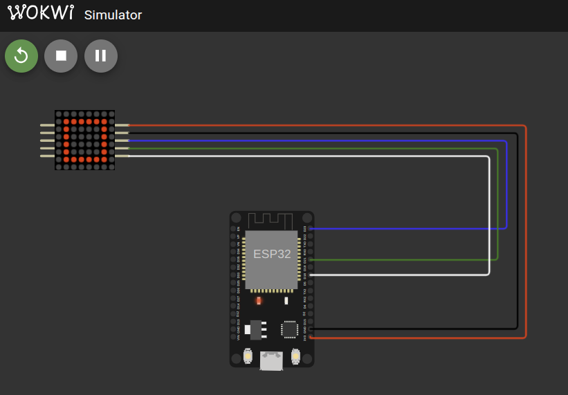
Implementing Embedded Graphics for Max7219 Rust Driver
In this chapter, we are not going to create a new driver from scratch. Instead, we will build on top of the Max7219 driver we already wrote. I think the Max7219 and the LED Matrix are a perfect choice to introduce you to the embedded-graphics crate. You can extend the Max7219 driver (similar to the max7219-display crate) we created in the previous chapter, or you can write this as a separate project that uses the Max7219 driver. The choice is yours.
Introduction to embedded-graphics
If you have ever played around with displays in embedded projects, you have probably wanted to do more than just turn pixels on and off. You may have already seen the embedded-graphics crate. Creating shapes or using different fonts on different displays is often a tedious process. Even something as simple as drawing a rectangle or a piece of text usually means writing a lot of code and keeping track of each pixel yourself.
This is where the embedded-graphics crate helps.
The embedded-graphics crate is a no-std, pure Rust graphics library designed for embedded environments. It uses a trait-based approach, similar to embedded-hal. A display driver developer (like us) implements the traits provided by embedded-graphics, and once that is done, you get access to many built-in utility features.
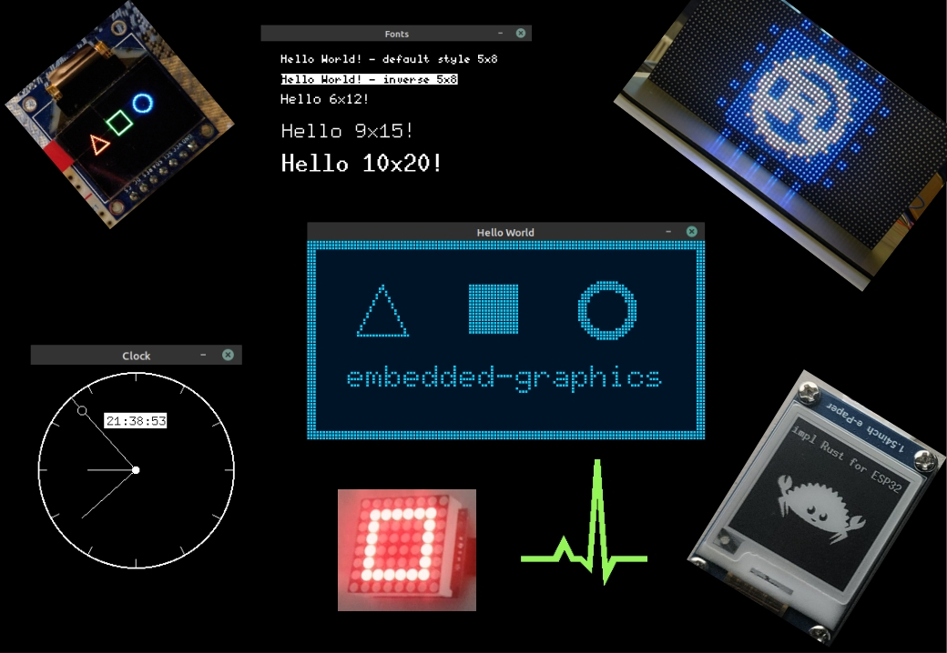
The nice part is that it works on many different types of displays. Crates like ssd1306 for OLED, ili9341 for TFT, and various e-ink drivers already support it, and the same code you write to draw text on an OLED can also work on a TFT or an e-ink display. You might need small adjustments if the display has different colors or resolutions, but the drawing code stays mostly the same. It is a lot like what embedded-hal does for hardware I/O, but this is for graphics.
Another big advantage is that embedded-graphics does not use a dynamic memory allocator. It uses an iterator-based approach to calculate pixel positions and colors on the fly. This keeps RAM usage low while still giving good performance.
In our case, we will implement embedded-graphics for our Max7219 LED matrix driver. Once we do that, we can draw patterns, shapes, and text using the same high-level commands that work on other displays. Instead of manually setting LEDs one by one, we simply describe what we want to draw and let embedded-graphics handle the rest.
The official embedded-graphics documentation explains the crate in much more detail than I can here. I recommend checking it out here.
Project Setup
I have cloned the max7219-driver-project that we completed in the previous chapter. I will work on the cloned version because I want to keep the original project intact as a reference for the previous chapter. But you can just work on the same repository you created for the MAX7219 driver.
git clone https://github.com/ImplFerris/max7219-driver-project max7219-eg
cd max7219-eg
code
Goal
We will create a new module called "led_matrix" and define a submodule "display" inside it. In display, we will define the LedMatrix struct and implement embedded-graphics support for it.
.
├── Cargo.toml
├── src
│   ├── driver
│   │   ├── max7219.rs
│   │   └── mod.rs
│   ├── error.rs
│   ├── led_matrix
│   │   ├── display.rs
│   │   └── mod.rs
│   ├── lib.rs
│   └── registers.rs
Implementing Embedded Graphics Core
So what do we have to implement in order to be compatible with embedded-graphics?
To add embedded-graphics support to a display driver, we must implement the DrawTarget trait from the embedded-graphics-core crate.
Note: This is not the same as the embedded-graphics crate that application developers normally use when they use the display crates. For driver development, you should use embedded-graphics-core instead.
The docs explain the required methods and types that we should define. You can read them here. Basically, we have to specify the supported Color type, the Error type, then implement the draw_iter method and the Dimensions trait. All other methods have default implementations that rely on these methods internally.
Update the Dependency
Add the embedded-graphics-core crate to your Cargo.toml:
embedded-graphics-core = { version = "0.4.0" }
Update the lib.rs
We will update the lib module to define the led_matrix module:
#![allow(unused)]
fn main() {
pub mod led_matrix;

// Dont forget to create led_matrix/mod.rs and led_matrix/display.rs files
}
LED Matrix
We will not implement embedded-graphics directly for the Max7219 struct because we want to keep it focused on core functions for both 7-segment and LED matrix control. Since embedded-graphics is not very useful for 7-segment displays, we'll create a separate struct called LedMatrix dedicated to LED matrix displays.
We will follow the minimum implementation example from the embedded-graphics-core crate. That example shows a fake display with a fixed size of 64x64 pixels. It defines a framebuffer as framebuffer: [u8; 64 * 64], with one u8 per pixel, so the buffer length is 4096 bytes. The example struct also includes an interface (iface) like SPI to send data to the display.
In our case, for the interface part, we will provide the Max7219 driver object that takes care of the SPI communication.
Framebuffer length
We can't fix the framebuffer length like that. For a single 8x8 LED matrix, the buffer length would be 64 bytes (8 * 8), but we want to support daisy-chained devices. The user might have a single LED matrix or 4 or 8 daisy-chained matrices.
-
For 4 daisy-chained matrices, the display size is 32x8 pixels, requiring a buffer length of 256.
-
For 8 daisy-chained matrices, it's 64x8 pixels, requiring a buffer length of 512.
NOTE: In the LED matrix, each pixel corresponds directly to one physical LED, represented by 1 byte per pixel in the framebuffer (for on/off).
So the framebuffer length must be dynamic depending on the number of chained devices. To solve this, we have different approaches:
-
Use a fixed-size buffer with a maximum supported size.
We can define a buffer large enough to handle the maximum number of chained matrices we expect to support (for example, 8 matrices -> 512 bytes). The buffer will always be this size, but we only use the part needed based on how many devices are connected.
The downside is that we over-allocate memory for setups with fewer matrices (like just 1 or 4 devices). -
Use heapless data structures.
Theheaplesscrate offers fixed-capacity containers likeVecandArrayVecthat work without dynamic allocation. This allows dynamic-length buffers within a fixed capacity.
However, this adds an external dependency, and I want to keep dependencies minimal; especially for a library.
(In fact, in my originalmax7219-displaycrate, I even putembedded-graphicsbehind a feature flag to keep it minimal and optional.) -
Use a generic const parameter for buffer size.
We can make theLedMatrixstruct generic over a const parameter representing the number of chained devices and total pixels. This lets us define the buffer size at compile time, avoiding dynamic allocation but still supporting different sizes.
So our final struct we will define it like this (in src/led_matrix/display.rs file)
#![allow(unused)]
fn main() {
pub struct LedMatrix<SPI, const BUFFER_LENGTH: usize = 64, const DEVICE_COUNT: usize = 1> {
    driver: Max7219<SPI>,
    /// Each 8x8 display has 64 pixels. For `N` daisy-chained devices,
    /// the total framebuffer size is `N * 64` pixels.
    ///
    /// For example, with 4 devices: `4 * 64 = 256` pixels.
    ///
    framebuffer: [u8; BUFFER_LENGTH],
}
}
Re-export the LedMatrix
Optionally, you can update the led_matrix/mod.rs file to re-export the LedMatrix struct. This makes it easier for end users to access it. Instead of using crate_name::led_matrix::display::LedMatrix, they can simply write crate_name::led_matrix::LedMatrix
To do this, add the following to led_matrix/mod.rs file:
#![allow(unused)]
fn main() {
mod display;

pub use display::LedMatrix;
}
Initialization
Let's get back to the display.rs module and implement some basic functions that will help initialize the LedMatrix struct.
#![allow(unused)]

fn main() {
impl<SPI, const BUFFER_LENGTH: usize, const DEVICE_COUNT: usize>
    LedMatrix<SPI, BUFFER_LENGTH, DEVICE_COUNT>
where
    SPI: SpiDevice,
{
    pub fn from_driver(driver: Max7219<SPI>) -> Result<Self> {
        if driver.device_count() != DEVICE_COUNT {
            return Err(Error::InvalidDeviceCount);
        }
        Ok(Self {
            driver,
            framebuffer: [0; BUFFER_LENGTH],
        })
    }

    pub fn driver(&mut self) -> &mut Max7219<SPI> {
        &mut self.driver
    }
}
}
We defined the from_driver function that accepts an already initialized Max7219 driver object. It verifies that the driver's device count matches the LedMatrix's expected device count, otherwise it returns an error. The framebuffer is initialized with zeros, sized by the BUFFER_LENGTH generic const parameter.
In my original max7219-display crate, I also implemented another convenience function from_spi to simplify initialization. It accepts a SpiDevice and creates the driver internally in one step.
The driver() method is straightforward: it returns a mutable reference to the driver. This lets users access and manipulate driver-level functions directly if needed.
Example initialization
For 4 daisy-chained devices:
#![allow(unused)]
fn main() {
let driver = Max7219::new(&mut spi_dev)
    .with_device_count(4)
    .expect("4 is valid count");

let display: LedMatrix<_, 256,4> = LedMatrix::from_driver(driver).expect("valid initialzation of the display");
}
For a single device, using default device count and buffer length:
#![allow(unused)]
fn main() {
let driver = Max7219::new(&mut spi_dev);
let display: LedMatrix<_> = LedMatrix::from_driver(driver).expect("valid initialization of the default display");
}
Tests
#![allow(unused)]
fn main() {
#[cfg(test)]
mod tests {
    use super::*;
    use crate::registers::Register;
    use embedded_hal_mock::eh1::spi::Mock as SpiMock;
    use embedded_hal_mock::eh1::spi::Transaction;

    #[test]
    fn test_from_driver() {
        let mut spi = SpiMock::new(&[]);
        let driver = Max7219::new(&mut spi);
        let matrix: LedMatrix<_, 64, 1> = LedMatrix::from_driver(driver).unwrap();
        assert_eq!(matrix.framebuffer, [0u8; 64]);
        spi.done();
    }

    #[test]
    fn test_driver_mut_access() {
        let expected_transactions = [
            Transaction::transaction_start(),
            Transaction::write_vec(vec![Register::Shutdown.addr(), 0x01]),
            Transaction::transaction_end(),
        ];
        let mut spi = SpiMock::new(&expected_transactions);
        let original_driver = Max7219::new(&mut spi);
        let mut matrix: LedMatrix<_> = LedMatrix::from_driver(original_driver).unwrap();

        let driver = matrix.driver();

        driver.power_on().expect("Power on should succeed");
        spi.done();
    }

}
}
Dimensions
Let's begin with the Dimensions trait. This trait is used by display drivers and drawable objects in embedded-graphics to describe the area they cover.
The Dimensions trait requires implementing one method called bounding_box. This method returns a Rectangle that defines the smallest rectangle fully enclosing the object or display.
What is Bounding box?
A bounding box is the smallest rectangle that completely contains the pixels of the object or display area you want to work with.
It is defined by two things:
-
The top-left corner position (an x and y coordinate), which marks where the rectangle starts on the display, and
-
The size (width and height), which tells how wide and tall the rectangle is.
You can think of it as drawing a frame around an object. Everything inside the frame belongs to the object, and everything outside is ignored.
The embedded-graphics requires this information so it can perform operations such as layout, collision detection, and transformations.

All primitive shapes in embedded-graphics (such as Rectangle, Circle, Triangle, and others) implement the Dimensions trait, which provides a bounding_box method.
For example, here is how Circle implements Dimensions:
#![allow(unused)]
fn main() {
impl Dimensions for Circle {
    fn bounding_box(&self) -> Rectangle {
        Rectangle::new(self.top_left, Size::new_equal(self.diameter))
    }
}
}
Normally, you create a Circle like this:
#![allow(unused)]
fn main() {
Circle::new(TOP_LEFT_POSITION, DIAMETER);
}
Using this information, the bounding_box method creates a Rectangle that fully contains the circle. With the bounding box, embedded-graphics can determine the shape's size and position, which allows it to handle tasks like collision checks, layout calculations, and deciding what part of the display needs to be redrawn.
Dimensions for Display
We are not going to implement the Dimensions trait directly. Instead, we will implement the OriginDimensions trait for the LedMatrix.
The reason is that embedded-graphics already provides a blanket implementation of Dimensions for every type that implements OriginDimensions:
#![allow(unused)]
fn main() {
impl<T> Dimensions for T
where
    T: OriginDimensions,
{
    fn bounding_box(&self) -> Rectangle {
        Rectangle::new(Point::zero(), self.size())
    }
}
}
🦀 In Rust, a blanket implementation is a way to automatically implement a trait for all types that meet certain conditions (like already implementing another trait), without writing separate code for each type.
For example, the standard library has an implementation written as
impl<T: Display> ToString for T. This means that every type that implements the Display trait gets acces to to_string() method. Because of this, String, i32, and any custom type that implements Display trait can call to_string() on it.In our case, any type that implements OriginDimensions automatically gets an implementation of Dimensions.
As you can see, embedded-graphics implements Dimensions for all types that implement OriginDimensions. The top_left point is always (x=0, y=0) because we are describing the whole display (like the LED matrix), which naturally starts at position (0, 0).
What remains is to define the size of our display. So for our LedMatrix, all we need to do is implement OriginDimensions and provide the size() method. The blanket implementation then ensures LedMatrix also implements Dimensions, with the bounding box starting at (0, 0) and using the size we specify.
Implementing for our LedMatrix
We will implement the OriginDimensions trait for our LedMatrix struct. This trait requires only one method size() which returns the size of the display area.
Since our LED matrix consists of multiple 8x8 devices daisy-chained horizontally, the width is DEVICE_COUNT * 8 pixels, and the height is always 8 pixels.
Update the disply.rs module with the following code.
Import the trait:
#![allow(unused)]
fn main() {
use embedded_graphics_core::prelude::{OriginDimensions};
}
Here's the implementation :
#![allow(unused)]
fn main() {
impl<SPI, const BUFFER_LENGTH: usize, const DEVICE_COUNT: usize> OriginDimensions
    for LedMatrix<SPI, BUFFER_LENGTH, DEVICE_COUNT>
{
    fn size(&self) -> Size {
        Size::new(DEVICE_COUNT as u32 * 8, 8)
    }
}
}
Tests
#![allow(unused)]
fn main() {
#[cfg(test)]
mod tests {
    use super::*;
    use crate::registers::Register;

    use embedded_graphics_core::{prelude::Point, primitives::Rectangle};
    use embedded_hal_mock::eh1::spi::Transaction;

    // ... Previous tests

    #[test]
    fn test_bounding_box() {
        const OUR_DEVICE_COUNT: usize = 2;
        const BUFFER_LENGTH_FOR_OUR_DEVICE: usize = 64 * OUR_DEVICE_COUNT;

        let mut spi = SpiMock::new(&[]);
        let driver = Max7219::new(&mut spi)
            .with_device_count(OUR_DEVICE_COUNT)
            .expect("2 is valid device count");

        let matrix: LedMatrix<_, BUFFER_LENGTH_FOR_OUR_DEVICE, OUR_DEVICE_COUNT> =
            LedMatrix::from_driver(driver).expect("driver is properly intialized");

        assert_eq!(
            matrix.bounding_box(),
            Rectangle::new(Point::new(0, 0), Size::new(16, 8))
        );

        spi.done();
    }
}
}
Implementing Draw Target for Max7219 LedMatrix
Next, we will implement the DrawTarget trait for our LedMatrix struct. This trait allows us to draw pixels and shapes onto the LED matrix using embedded-graphics APIs.
Required imports:
#![allow(unused)]
fn main() {
use embedded_graphics_core::geometry::Dimensions;
use embedded_graphics_core::pixelcolor::BinaryColor;
use embedded_graphics_core::prelude::{DrawTarget, OriginDimensions, Size};
}
Here is the full implementation of the DrawTarget trait for our LedMatrix (add this in the display.rs module). We implement the draw_iter function that takes an iterator of pixels to draw.
We set the Color type to BinaryColor because the LED matrix supports only on and off states. We then set the Error type to core::convert::Infallible since all drawing operations modify only the local framebuffer. No hardware communication happens during drawing, so there is no possibility of errors at this stage. This means our drawing operations are infallible and guaranteed to succeed.
#![allow(unused)]

fn main() {
impl<SPI, const BUFFER_LENGTH: usize, const DEVICE_COUNT: usize> DrawTarget
    for LedMatrix<SPI, BUFFER_LENGTH, DEVICE_COUNT>
where
    SPI: SpiDevice,
{
    type Color = BinaryColor;
    type Error = core::convert::Infallible;

    fn draw_iter<I>(&mut self, pixels: I) -> core::result::Result<(), Self::Error>
    where
        I: IntoIterator<Item = Pixel<Self::Color>>,
    {
        let bb = self.bounding_box();
        for Pixel(pos, color) in pixels.into_iter() {
            if bb.contains(pos) {
                let device_index = (pos.x as usize) / 8;
                let col = (pos.x as usize) % 8;
                let row = pos.y as usize;

                if device_index < DEVICE_COUNT && row < 8 && col < 8 {
                    let index = device_index * 64 + row * 8 + col;
                    if index < self.framebuffer.len() {
                        self.framebuffer[index] = color.is_on() as u8;
                    }
                }
            }
        }

        // Note: Does not call self.flush() automatically.
        Ok(())
    }
}
}
How It looks on the Display?
Before I explain the code, let me quickly show you how the embedded-graphics coordinates map to the physical LED matrix layout.
From the embedded-graphics point of view, all the daisy-chained devices together form one big display. The pixel at coordinate (0, 0) corresponds to the first LED on the leftmost device in the chain.
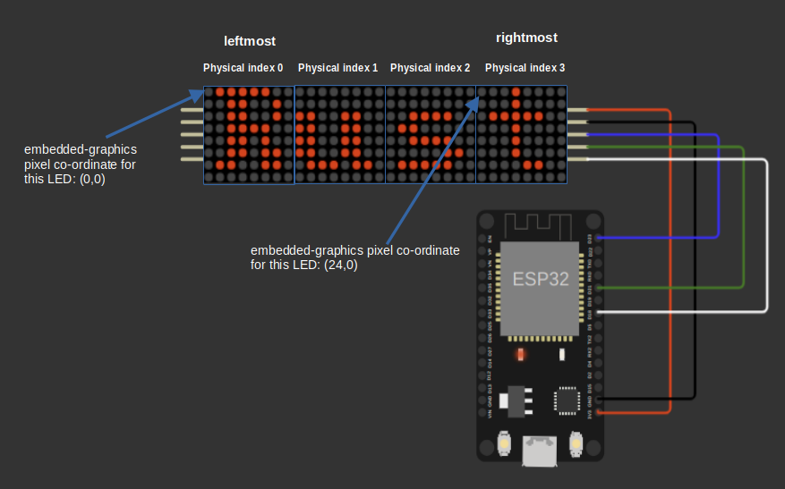
In the case of 4 daisy-chained devices, each device is 8 pixels wide, so the total width is 4 × 8 = 32 pixels. The pixel at coordinate (24, 0) corresponds to the first LED on the rightmost device, which is the one closest to the microcontroller.
So, the coordinates start at the left and increase to the right, from the leftmost device to the rightmost device.
Device and Position Calculation
First, we get the bounding box of the display to know the valid drawing area. Then, for each pixel provided by the iterator, we check if the pixel's position lies inside this bounding box.
#![allow(unused)]
fn main() {
//  Code snippet
if bb.contains(pos) {
    let device_index = (pos.x as usize) / 8;
    let col = (pos.x as usize) % 8;
    let row = pos.y as usize;

    // rest of the code...
}
}
Next, we find out which device the pixel belongs to by dividing its x-coordinate by 8. Each device is one 8-pixel-wide LED matrix device connected in a chain.
The column within that device is the remainder when dividing the x-coordinate by 8, and the row is simply the y-coordinate.
For example, if the pixel position is (5, 2), dividing 5 by 8 gives 0, so the pixel belongs to device 0. The remainder of this division (5 % 8) is 5, which gives the column position within that device. The row position directly maps to the y value, which is 2.
Updating Pixel State in the Framebuffer
Next, we verify that the calculated device number, row, and column are within valid ranges: the device must be less than the total number of devices, and the row and column must be less than 8 because each device is an 8x8 matrix.
I have created this image to illustrate the framebuffer layout for four daisy-chained devices, making it easier to understand how the indexing works.

After confirming the indices are valid, we calculate the linear index into the framebuffer. The framebuffer is stored as a flat array, with each device using 64 bytes (8 rows × 8 columns). The first 64 entries belong to the first device, the next 64 entries belong to the second device, and so on. To compute the index, we multiply the device number by 64, add the row offset (row × 8), and then add the column offset.
#![allow(unused)]
fn main() {
// Code snippet
let index = device_index * 64 + row * 8 + col;
if index < self.framebuffer.len() {
    self.framebuffer[index] = color.is_on() as u8;
}
}
Finally, if the index is within the framebuffer length, we set the framebuffer byte at that index to 1 if the pixel color is on, or 0 if it is off. This updates the local framebuffer to reflect the pixel changes requested by the draw operation.
If we apply this to the example pixel position (5, 2), where device_index = 0, row = 2, and col = 5, the index is calculated as:
#![allow(unused)]
fn main() {
index = 0 * 64 + 2 * 8 + 5 = 21
}
This means we update the 21st byte in the framebuffer array to turn the pixel on or off, depending on the color.is_on() value. Now, if you cross check with Figure 2, you will find that framebuffer index 21 is located at column 5 (counting from 0) and row 2.
Tests
#![allow(unused)]
fn main() {
#[cfg(test)]
mod tests {
    use super::*;
    use crate::registers::Register;

    use embedded_graphics_core::{prelude::Point, primitives::Rectangle};
    use embedded_hal_mock::eh1::spi::Mock as SpiMock;
    use embedded_hal_mock::eh1::spi::Transaction;

    // ... Previous tests

    #[test]
    fn test_draw_target_draw_iter() {
        let mut spi = SpiMock::new(&[]);
        let driver = Max7219::new(&mut spi);
        let mut matrix: LedMatrix<_> = LedMatrix::from_driver(driver).unwrap(); // 1 device, 64 pixels

        // Define some pixels to draw
        let pixels = [
            Pixel(Point::new(0, 0), BinaryColor::On), // Device 0, Row 0, Col 0
            Pixel(Point::new(1, 0), BinaryColor::Off), // Device 0, Row 0, Col 1
            Pixel(Point::new(7, 7), BinaryColor::On), // Device 0, Row 7, Col 7
            // out of bounds
            Pixel(Point::new(8, 0), BinaryColor::On),
            Pixel(Point::new(0, 8), BinaryColor::On),
            Pixel(Point::new(20, 20), BinaryColor::On),
        ];

        // Draw the pixels
        matrix.draw_iter(pixels.iter().cloned()).unwrap();

        let mut expected = [0u8; 64];
        expected[0] = 1; // (0, 0) ON
        expected[1] = 0; // (1, 0) OFF
        expected[63] = 1; // (7, 7) ON

        assert_eq!(&matrix.framebuffer, &expected);

        spi.done();
    }

    #[test]
    fn test_draw_target_draw_iter_multi_device() {
        let mut spi = SpiMock::new(&[]);
        let driver = Max7219::new(&mut spi).with_device_count(2).unwrap(); // 2 devices
        let mut matrix: LedMatrix<_, 128, 2> = LedMatrix::from_driver(driver).unwrap(); // 2 devices, 128 pixels

        // Define some pixels to draw across devices
        let pixels = [
            // x=0 -> device = 0/8 = 0
            // col = 0%8 = 0
            // row = 0
            // index = device*64 + row*8 + col = 0*64 + 0*8 + 0 = 0
            Pixel(Point::new(0, 0), BinaryColor::On),
            // x=7 -> device = 7/8 = 0
            // col = 7%8 = 7
            // row = 0
            // index = 0*64 + 0*8 + 7 = 7
            Pixel(Point::new(7, 0), BinaryColor::On),
            // x=8 -> device = 8/8 = 1
            // col = 8%8 = 0
            // row = 1
            // index = device*64 + row*8 + col = 1*64 + 1*8 + 0 = 64 + 8 + 0 = 72
            Pixel(Point::new(8, 1), BinaryColor::On),
            // x=15 -> device = 15/8 = 1
            // col = 15%8 = 7
            // row = 7
            // index = 1*64 + 7*8 + 7 = 64 + 56 + 7 = 127
            Pixel(Point::new(15, 7), BinaryColor::On),
        ];

        // Draw the pixels
        matrix.draw_iter(pixels.iter().cloned()).unwrap();

        // Check framebuffer state
        let mut expected = [0u8; 128];
        expected[0] = 1; // Device 0, Col 0, Row 0
        expected[7] = 1; // Device 0, Col 7, Row 0
        expected[72] = 1; // Device 1, Col 0, Row 1
        expected[127] = 1; // Device 1, Col 7, Row 7

        assert_eq!(&matrix.framebuffer, &expected);

        spi.done();
    }

}
}
Flushing the Framebuffer to the Max7219 LED Matrix
We have successfully implemented embedded-graphics for the LedMatrix, and now we need to update the actual LED matrix hardware with the pixel data stored in our internal framebuffer. For this, we will define a method called "flush".
Required imports
#![allow(unused)]
fn main() {
use crate::registers::Register;
use crate::Result;
}
The flush method sends data row by row (from row 0 to row 7) to all daisy-chained devices. For each row, it prepares an array of SPI commands; one per device that represent that row's pixels packed into a single byte.
#![allow(unused)]
fn main() {
impl<SPI, const BUFFER_LENGTH: usize, const DEVICE_COUNT: usize>
    LedMatrix<SPI, BUFFER_LENGTH, DEVICE_COUNT>
where
    SPI: SpiDevice,
{
    // ...other functions like from_driver that we created before

    pub fn flush(&mut self) -> Result<()> {
        for (row, digit_register) in Register::digits().enumerate() {
            let mut ops = [(Register::NoOp, 0); DEVICE_COUNT];

            for (device_index, op) in ops.iter_mut().enumerate() {
                let buffer_start = device_index * 64 + row * 8;
                let mut packed_byte = 0b0000_0000;

                for col in 0..8 {
                    let pixel_index = buffer_start + col;
                    if pixel_index < self.framebuffer.len() && self.framebuffer[pixel_index] != 0 {
                        // bit 7 is leftmost pixel (Col 0) on the display
                        packed_byte |= 1 << (7 - col);
                    }
                }

                *op = (digit_register, packed_byte);
            }

            self.driver.write_all_registers(&ops[..DEVICE_COUNT])?;
        }
        Ok(())
    }
}
}
Let's walk through the code step-by-step:
Batched SPI Commands
We send SPI commands in batches; one SPI transaction per row regardless of the number of devices. So, at the top-level loop, we iterate over the Digit Registers (from 0 to 7), representing each row of the display.
#![allow(unused)]
fn main() {
for (row, digit_register) in Register::digits().enumerate() {
}
We create an array named ops to hold SPI commands for each device. Initially, each command is set to a No-Op with a data byte of 0. The size of this array equals the number of connected devices.
#![allow(unused)]
fn main() {
let mut ops = [(Register::NoOp, 0); DEVICE_COUNT];
}
Finding the Column Start Position for the Current Row
Next, we determine which columns correspond to the current row for each device by reading from the framebuffer. We loop through all devices and calculate the starting position in the framebuffer for each device and row.
We calculate buffer_start using the formula:
#![allow(unused)]
fn main() {
let buffer_start = device_index * 64 + row * 8;
}
Each device's section of the framebuffer is 64 bytes (8 rows × 8 columns). Multiplying the device index by 64 takes us to the start of that device's section. Then, row * 8 moves us down to the specific row inside that device.
For example, if we are processing the second row (row index 1) of the third device (device_index 2), the buffer start is:
#![allow(unused)]
fn main() {
2 * 64 + 1 * 8 = 128 + 8 = 136
}
You can verify this position against the illustration above, where the buffer_start matches the row and device's location in the framebuffer.
Building the Data Packet
Now that we know the starting column position for the current row and device, we need to create the data packet representing which pixels in this row are turned on or off.
For each device, we extract the 8 pixels of the current row from the framebuffer. These 8 pixels are packed into a single byte, where bit 7 corresponds to the leftmost pixel (column 0), and bit 0 corresponds to the rightmost pixel (column 7).
We start by initializing a byte with all bits set to zero. This byte will hold the pixel states for the 8 columns in the current row:
#![allow(unused)]
fn main() {
let mut packed_byte = 0b0000_0000;
}
Next, we loop over each column (from 0 to 7). For each column, we calculate the pixel's index in the framebuffer by adding buffer_start + col. If the pixel at that index is ON (i.e non-zero), we set the corresponding bit in packed_byte. Because bit 7 is the leftmost pixel, the bit to set is 7 - col:
#![allow(unused)]
fn main() {
for col in 0..8 {
    let pixel_index = buffer_start + col;
    if pixel_index < self.framebuffer.len() && self.framebuffer[pixel_index] != 0 {
        // bit 7 is leftmost pixel (Col 0) on the display
        packed_byte |= 1 << (7 - col);
    }
}
}
For example, suppose the framebuffer values for a given row and device's columns are: [1, 0, 1, 0, 1, 0, 1, 0]
This would be packed as:
| Bit 7 | Bit 6 | Bit 5 | Bit 4 | Bit 3 | Bit 2 | Bit 1 | Bit 0 |
|---|---|---|---|---|---|---|---|
| 1 | 0 | 1 | 0 | 1 | 0 | 1 | 0 |
Resulting in a binary value of 0b10101010.
SPI Operations
Now that we have the digit register (row), device index, and packed data byte representing the pixels, we can prepare the SPI operation array to send this data to the devices.
For each device, we create a tuple of (digit_register, packed_byte):
#![allow(unused)]
fn main() {
*op = (digit_register, packed_byte);
}
After processing all devices for the current row, the ops array will contain an entry for each device, something like this (assuming 4 devices):
#![allow(unused)]
fn main() {
[
    (digit_register, packed_byte_device_0),
    (digit_register, packed_byte_device_1),
    (digit_register, packed_byte_device_2),
    (digit_register, packed_byte_device_3),
]
}
Finally, we send all the prepared operations for the current row in a single SPI transaction:
#![allow(unused)]
fn main() {
self.driver.write_all_registers(&ops[..DEVICE_COUNT])?;
}
This process is repeated for each row until the entire framebuffer is sent to the devices.
Tests
#![allow(unused)]
fn main() {
#[test]
fn test_flush_single_device() {
    // We expect the flush to send 8 SPI transactions, one for each row (DIGIT0 to DIGIT7)
    // Only rows 0 and 7 have pixel data: 0b10101010 (columns 0,2,4,6 lit)
    // All other rows should be cleared (0b00000000)

    let mut expected_transactions = Vec::new();
    for (row, digit_register) in Register::digits().enumerate() {
        // For rows 0 and 7, the framebuffer will result in this pattern:
        // Columns 0, 2, 4, 6 are ON => bits 7, 5, 3, 1 set => 0b10101010
        let expected_byte = if row == 0 || row == 7 {
            0b10101010
        } else {
            0b00000000
        };

        // Each transaction sends [register, data] for that row
        expected_transactions.push(Transaction::transaction_start());
        expected_transactions.push(Transaction::write_vec(vec![
            digit_register.addr(),
            expected_byte,
        ]));
        expected_transactions.push(Transaction::transaction_end());
    }

    // Create the SPI mock with the expected sequence of writes
    let mut spi = SpiMock::new(&expected_transactions);
    let driver = Max7219::new(&mut spi);
    let mut matrix: LedMatrix<_> = LedMatrix::from_driver(driver).unwrap();

    // Set framebuffer values to light up alternating columns in row 0 and row 7
    // Row 0 corresponds to framebuffer indices 0 to 7
    matrix.framebuffer[0] = 1; // Column 0
    matrix.framebuffer[2] = 1; // Column 2
    matrix.framebuffer[4] = 1; // Column 4
    matrix.framebuffer[6] = 1; // Column 6

    // Each device's framebuffer is a flat array of 64 bytes: 8 rows * 8 columns
    // The layout is row-major: [row0[0..7], row1[0..7], ..., row7[0..7]]
    //
    // For a single device:
    //   framebuffer[ 0.. 7] => row 0
    //   framebuffer[ 8..15] => row 1
    //   framebuffer[16..23] => row 2
    //   framebuffer[24..31] => row 3
    //   framebuffer[32..39] => row 4
    //   framebuffer[40..47] => row 5
    //   framebuffer[48..55] => row 6
    //   framebuffer[56..63] => row 7 (last row)
    //
    // So to update row 7, we write to indices 56 to 63.
    matrix.framebuffer[56] = 1; // Column 0
    matrix.framebuffer[58] = 1; // Column 2
    matrix.framebuffer[60] = 1; // Column 4
    matrix.framebuffer[62] = 1; // Column 6

    // Call flush, which will convert framebuffer rows into bytes and send via SPI
    let result = matrix.flush();
    assert!(result.is_ok());

    spi.done();
}

#[test]
fn test_flush_multiple_devices() {
    const TEST_DEVICE_COUNT: usize = 4;
    const TEST_BUFF_LEN: usize = 256;

    let mut expected_transactions = Vec::new();

    for (row, digit_register) in Register::digits().enumerate() {
        expected_transactions.push(Transaction::transaction_start());

        // For each device, we write the register and data byte

        let ops_array = (0..TEST_DEVICE_COUNT)
            .flat_map(|device| {
                let expected_byte = match (row, device) {
                    (0, 0) => 0b10101000,
                    (7, 2) => 0b00010101,
                    _ => 0b0000_0000,
                };
                vec![digit_register.addr(), expected_byte]
            })
            .collect();

        expected_transactions.push(Transaction::write_vec(ops_array));

        expected_transactions.push(Transaction::transaction_end());
    }

    // Create SPI mock with expected transactions
    let mut spi = SpiMock::new(&expected_transactions);
    let driver = Max7219::new(&mut spi)
        .with_device_count(TEST_DEVICE_COUNT)
        .unwrap();

    let mut matrix: LedMatrix<_, TEST_BUFF_LEN, TEST_DEVICE_COUNT> =
        LedMatrix::from_driver(driver).unwrap();

    // Set pixels for device 0
    matrix.framebuffer[0] = 1; // row 0, col 0
    matrix.framebuffer[2] = 1; // row 0, col 2
    matrix.framebuffer[4] = 1; // row 0, col 4

    // Set pixels for device 2
    matrix.framebuffer[64 * 2 + 7 * 8 + 3] = 1; // row 7, col 3
    matrix.framebuffer[64 * 2 + 7 * 8 + 5] = 1; // row 7, col 5
    matrix.framebuffer[64 * 2 + 7 * 8 + 7] = 1; // row 7, col 7

    // Call flush, which converts framebuffer rows into bytes and sends via SPI
    let result = matrix.flush();
    assert!(result.is_ok());

    spi.done();
}
}
Clear Pixels
We have created functions to draw on the framebuffer, then push the framebuffer to the display. There is one more thing missing, we should provide capability to clear the local framebuffer or clear the screen (i.e clear the framebuffer and push it to the devices).
The clear_buffer() function simply fills the framebuffer with zeros, effectively turning off all pixels in memory. This is useful when you want to prepare a clean slate for drawing new content.
#![allow(unused)]
fn main() {
pub fn clear_buffer(&mut self) {
    self.framebuffer.fill(0);
}
}
The clear_screen() function does two things: it clears the framebuffer and immediately flushes the changes to the display. This is what you want when you need to clear what's currently showing on the LED matrix.
#![allow(unused)]
fn main() {
pub fn clear_screen(&mut self) -> Result<()> {
    self.clear_buffer();
    self.flush()
}
}
The completed Project
The completed project, which implements the embedded-graphics with the max7219-driver, is available here:
https://github.com/ImplFerris/max7219-eg
Tests
#![allow(unused)]
fn main() {
#[test]
fn test_clear_buffer() {
    let mut spi = SpiMock::new(&[]); // No SPI interaction
    let driver = Max7219::new(&mut spi);
    let mut matrix = SingleMatrix::from_driver(driver).unwrap();

    // Modify the buffer
    matrix.framebuffer[0] = 1;
    matrix.framebuffer[10] = 1;
    matrix.framebuffer[63] = 1;
    assert_ne!(matrix.framebuffer, [0u8; 64]);

    matrix.clear_buffer();

    assert_eq!(matrix.framebuffer, [0u8; 64]);
    spi.done();
}

#[test]
fn test_clear_screen() {
    // All digits 0..7 will be written with 0x00 for a single device
    let mut expected_transactions = Vec::new();
    for row in 0..8 {
        let digit_register = Register::try_digit(row).unwrap();
        expected_transactions.push(Transaction::transaction_start());
        expected_transactions.push(Transaction::write_vec(vec![digit_register.addr(), 0x00]));
        expected_transactions.push(Transaction::transaction_end());
    }

    let mut spi = SpiMock::new(&expected_transactions);
    let driver = Max7219::new(&mut spi);
    let mut matrix = SingleMatrix::from_driver(driver).unwrap();

    // Modify the buffer
    matrix.framebuffer[5] = 1;
    matrix.framebuffer[15] = 1;

    assert_ne!(matrix.framebuffer, [0u8; 64]);

    let result = matrix.clear_screen();
    assert!(result.is_ok());
    assert_eq!(matrix.framebuffer, [0u8; 64]);
    spi.done();
}
}
Using with ESP32
Now that we have successfully implemented the embedded-graphics for our LED Matrix, it is time to put it to the test. I will be showing how to test it on a single LED Matrix (FC-16 module with 1088AS). You can use daisy-chained LED matrices also and try.
Circuit
Here's a simple circuit connection for wiring the FC-16 MAX7219 LED matrix module to an ESP32.
| FC-16 (MAX7219 Module) Pin | ESP32 Pin | Notes |
|---|---|---|
| VCC | 3.3V or 5V | Power supply |
| GND | GND | Ground |
| DIN (Data In) | GPIO23 (MOSI) | SPI Master Out |
| CLK (Clock) | GPIO18 (SCK) | SPI Clock |
| CS (Chip Select) | GPIO21 | SPI Chip Select (CS) |
⚠️ Important: If you are using daisy-chained LED matrices, do not power the LED matrix from the microcontroller's 3.3V or 5V pin directly.
Use a separate external 5V power supply to power the LED matrices.
Failing to do so can damage your microcontroller or the LED matrices due to high current draw. Always connect the grounds of both power supplies together to have a common reference.
Add the Crate as a Dependency
Create new project with esp-generate tool and add your Git repository as a dependency in your Cargo.toml:
embedded-hal-bus = "0.3.0"

# Full Crate
# max7219-display = { git = "https://github.com/ImplFerris/max7219-display", features = [] }

# Bare driver for the Red book:
max7219-eg = { git = "https://github.com/ImplFerris/max7219-eg" }
Full code
In this example, we will use embedded-graphics to draw a square, then a circle inside the square without clearing the display. Then clear the screen and display the character "R".
#![no_std]
#![no_main]
#![deny(
    clippy::mem_forget,
    reason = "mem::forget is generally not safe to do with esp_hal types, especially those \
    holding buffers for the duration of a data transfer."
)]

use defmt::info;
use embedded_graphics::mono_font::ascii::FONT_5X8;
use embedded_graphics::mono_font::MonoTextStyle;
use embedded_graphics::pixelcolor::BinaryColor;
use embedded_graphics::prelude::*;
use embedded_graphics::prelude::{Point, Primitive, Size};
use embedded_graphics::primitives::{Circle, PrimitiveStyleBuilder, Rectangle};
use embedded_graphics::text::{Text, TextStyleBuilder};
use esp_hal::clock::CpuClock;
use esp_hal::delay::Delay;
use esp_hal::main;
use esp_hal::time::{Duration, Instant};
use esp_println as _;

use embedded_hal_bus::spi::ExclusiveDevice;
use esp_hal::gpio::{Level, Output, OutputConfig};
use esp_hal::spi::master::Config as SpiConfig;
use esp_hal::spi::master::Spi;
use esp_hal::spi::Mode as SpiMode;
use esp_hal::time::Rate;
use max7219_eg::driver::Max7219;
use max7219_eg::led_matrix::LedMatrix;

#[panic_handler]
fn panic(_: &core::panic::PanicInfo) -> ! {
    loop {}
}

esp_bootloader_esp_idf::esp_app_desc!();

#[main]
fn main() -> ! {
    // generator version: 0.4.0

    let config = esp_hal::Config::default().with_cpu_clock(CpuClock::max());
    let peripherals = esp_hal::init(config);

    let spi = Spi::new(
        peripherals.SPI2,
        SpiConfig::default()
            .with_frequency(Rate::from_mhz(10))
            .with_mode(SpiMode::_0),
    )
    .unwrap()
    //CLK
    .with_sck(peripherals.GPIO18)
    //DIN
    .with_mosi(peripherals.GPIO23);
    let cs = Output::new(peripherals.GPIO21, Level::High, OutputConfig::default());

    let spi_dev = ExclusiveDevice::new_no_delay(spi, cs).unwrap();

    let mut driver = Max7219::new(spi_dev);
    driver.init().unwrap();
    let mut display: LedMatrix<_> = LedMatrix::from_driver(driver).expect("valid device count");

    let delay = Delay::new();

    // --- Draw Square ---
    let square = PrimitiveStyleBuilder::new()
        .stroke_color(BinaryColor::On) // Only draw the border
        .stroke_width(1) // Border thickness of 1 pixel
        .build();
    let rect = Rectangle::new(Point::new(1, 1), Size::new(6, 6)).into_styled(square);
    rect.draw(&mut display).unwrap();
    display.flush().unwrap();

    delay.delay_millis(1000);

    // Uncomment to Clear the screen and buffer
    // Without this, it will draw the circle inside the previous square
    // display.clear_screen().unwrap();

    // --- Draw Circle ---
    let hollow_circle_style = PrimitiveStyleBuilder::new()
        .stroke_color(BinaryColor::On)
        .stroke_width(1)
        .build();
    let circle = Circle::new(Point::new(2, 2), 4).into_styled(hollow_circle_style);
    circle.draw(&mut display).unwrap();
    display.flush().unwrap();

    delay.delay_millis(1000);

    // Just clear the buffer. it wont send request to the devices until the flush.
    display.clear_buffer();

    //  Write Text (in single device, just a character)
    let text_style = TextStyleBuilder::new()
        .alignment(embedded_graphics::text::Alignment::Center)
        .baseline(embedded_graphics::text::Baseline::Top)
        .build();
    let character_style = MonoTextStyle::new(&FONT_5X8, BinaryColor::On);
    let text = Text::with_text_style("R", Point::new(4, 0), character_style, text_style);
    text.draw(&mut display).unwrap();
    display.flush().unwrap();

    loop {
        info!("Hello world!");
        let delay_start = Instant::now();
        while delay_start.elapsed() < Duration::from_millis(500) {}
    }

}
Clone Existing Project
If you want to get started quickly, you can clone a ready-to-use example project from my repository:
git clone https://github.com/implferris/max7219-esp32-eg
cd max7219-esp32-eg
This project includes Wokwi configuration, so you can test it with the MAX7219 LED matrix virtually, right inside VSCode using the Wokwi simulator. No physical hardware needed to get started. Just install the Wokwi extension for VSCode and run the project to see the LED matrix in action. For details, visit https://docs.wokwi.com/vscode/getting-started.

Real Time Clock
Have you ever wondered how your computer, phone, or even your microwave keeps track of time even when it's unplugged? That's where Real Time Clock (RTC) modules come in. It is a kind of watch but tiny in size which will be used with microcontrollers and computers.
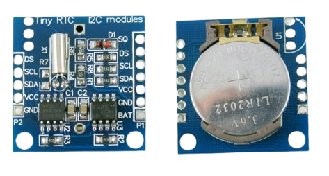
The DS1307 is one of the most popular and cheap RTC modules you can buy. It does basic timekeeping and works well for most projects where you don't need perfect accuracy.
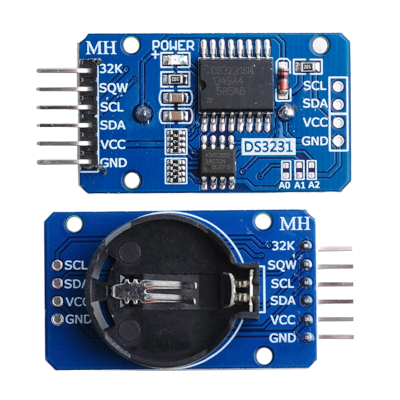
The DS3231 costs a bit more than the DS1307 but it's much more accurate. RTC like the DS1307 can lose or gain time because temperature changes mess with their timing. When it gets hot or cold, the clock runs fast or slow. The DS3231 fixes this problem by watching the temperature and adjusting itself automatically. It also has extra features like alarms that can wake up your microcontroller at set times.
What Makes RTCs Special?
One of the best things about an RTC is that it can keep running even if your main power is turned off. This is possible because it has a small backup power source. Some modules usually use a coin-cell lithium battery for this, while others may use a tiny rechargeable part called a supercapacitor. It is just like a wristwatch that runs on a battery. Since RTCs use very little power, that backup can keep them running for months or even years without needing a recharge or replacement.
I2C Communication
Both modules use I2C communication. It's one of the reasons I chose them because I want to write one chapter that uses I2C. Once we write the driver for the DS1307, the DS3231 will be much simpler since most of the communication is the same.
What We'll Build
At first, I planned to write separate drivers for the DS1307 and DS3231. But then I found the "rtcc" crate, which uses a smart approach with traits. This gave me a better idea.
Instead of just making two separate drivers, we'll build something more interesting. We'll create our own RTC HAL that can work with any RTC module. Here's what we'll do:
- Create a RTC HAL crate that defines generic RTC traits; This will define what any RTC should be able to do
- Build drivers for DS1307 and DS3231 that both implement the RTC HAL traits
- Finally i will show you a demo app that works with either module using the same code
The cool part is that our test program won't care which RTC chip you use. This means the same code will work whether you connect a DS1307, DS3231, or any other RTC chip(that implements our RTC HAL trait). You can change the RTC and everything still works.
Finished Project
Here's the final project for reference.
This demo app(end-user example) uses different RTC drivers (DS1307 and DS3231) with RTC HAL traits: http://github.com/implferris/rtc-hal-demo
These driver crates implements RTC HAL traits:
- DS1307 RTC Driver: https://github.com/implferris/ds1307-rtc
- DS3231 RTC Driver: https://github.com/implferris/ds3231-rtc
The rtc-hal trait (the foundation, like embedded-hal crate): https://github.com/implferris/rtc-hal
I listed this project backwards - starting from the end user view, then working back to rtc-hal. This shows you the big picture of how it all works together. But in the chapter, we'll start from rtc-hal because that's the foundation, and then moving upward.
Real-Time Clock (RTC) Hardware Abstraction Layer (HAL)
In this chapter, we'll develop an RTC HAL crate that provides generic traits for Real Time Clock (RTC) functionality. Our design follows the embedded-hal design pattern, creating a standardized interface that can work across different RTCs.
Note: This is just one approach to structuring an RTC HAL. While I've researched and structured this design carefully, it may not be perfect. If you're designing a similar HAL, consider conducting additional research and maybe do better design than this. But this chapter will show you the basics and how I did it.
Prerequisites
In order to design the RTC HAL, we need to research and find what are the common functionalities of RTCs. We have to look at the datasheet of different RTC chips (in our case, I just referred to the DS1307 and DS3231). After going through them, I found these basic functions that RTCs support.
Core RTC Functions
-
Date Time Support: Obviously, this is the whole point of having an RTC. We should be able to set the date and time, and read back the current time whenever we need it. This is the most essential function in any RTC.
-
Square Wave Support: If you've looked at the datasheets, you'll see they mention Square Wave functionality. This lets the RTC generate clock signals at various frequencies like 1Hz, 4kHz, 8kHz, or 32kHz. These signals are handy for system timing, triggering interrupts, or providing clock signals to other components.
-
Power Control: Basic stuff like starting and stopping the clock.
RTC Specific Features
Different RTC chips come with their own unique features:
-
Non-volatile RAM: DS1307 has this feature which allows us to store 56 bytes of data that stays powered by the backup battery. This is useful for storing configuration data or small amount of information. The DS3231 doesn't have this.
-
Alarm: The DS3231 has two independent alarm systems. You can configure them for different time and date combinations, and they can generate interrupts to wake up your system or trigger events. The DS1307 doesn't support alarms.
What This Means for Our Design
We can't put all these functions into a single trait - we need it to be flexible. Even the core functions like square wave, I wasn't entirely sure if all RTCs support them. So I designed it in a way that splits up the traits.
We'll have a core trait called Rtc that handles the basic date and time functions. The RTC driver must implement this trait.
Then we'll have separate traits for different features: RtcPowerControl, SquareWave, and RtcNvram. These feature traits require the core Rtc trait, so any RTC that supports these features automatically has the basic functionality too.
For now, I'm not including the alarm trait in this design but will add it later (you can also try this as an exercise). The alarm system would take more sections to explain properly, so I want to keep things simple for now.
This isn't a perfect or final design. I actually tried different approaches with naming, error handling, and overall structure, and ended up modifying it multiple times. I finally settled on this design "for now".
Project Setup
This is what we are aiming for:
.
├── Cargo.toml
├── README.md
└── src
    ├── alarm.rs
    ├── bcd.rs
    ├── control.rs
    ├── datetime.rs
    ├── error.rs
    ├── lib.rs
    ├── nvram.rs
    ├── rtc.rs
    └── square_wave.rs
Each module corresponds to different parts of our RTC HAL design. The rtc.rs contains our core trait, while square_wave.rs, nvram.rs, and control.rs handle the feature-specific traits. The datetime.rs module deals with date and time types, bcd.rs provides utillity functions for Binary Coded Decimal conversions (since most RTCs work with BCD internally), and error.rs defines our error types. Even though we're not covering alarms in this section, I've included alarm.rs for future implementation (it is just with comment "//TODO").
If you want to see the completed project, you can have a look at the rtc-hal project here
Create new library
Let's initialize a new Rust library project.
cargo new rtc-hal --lib
cd rtc-hal
Feel free to rename the project name. You can create all the necessary files and modules with placeholder content upfront, or create them as we go along.
Finally the main module(lib.rs) will have this
#![allow(unused)]
fn main() {
pub mod alarm;
pub mod bcd;
pub mod control;
pub mod datetime;
pub mod error;
pub mod nvram;
pub mod rtc;
pub mod square_wave;
}
Configuring Dependencies
For this library, we'll include defmt as an optional dependency to provide structured logging capabilities. We will put this dependency behind feature flag, so users can choose whether to include defmt support in their builds, keeping the library lightweight for those who don't need it.
Update your Cargo.toml with the following:
[dependencies]
defmt = { version = "1.0.1", optional = true }

[features]
defmt = ["dep:defmt"]
Error Types
Before we can define methods for our RTC traits, we need to figure out how to handle errors. We'll use the same approach as embedded-hal.
Evolution of Error Handling in embedded-hal
Before version 1.0, embedded-hal used an associated Error type in each trait. This was simple but caused problems; drivers couldn't easily work with errors in a generic way since each HAL had its own error enum.
In version 1.0, embedded-hal introduced a new model. HALs can still define their own error enums, but those error types must implement a common Error trait that exposes a standardized ErrorKind. This allows applications and generic drivers to inspect errors in a portable way, independent of the underlying implementation.
Example Problematic Code
Looking at this example code, you can see the problem with just using associated types. Driver1 and Driver2 each define their own error enums.
In application code that works with any RTC driver, you can only print the error or check if one occurred. But you can't inspect what specific error happened.
If you want to take different actions based on the error type - like retrying on InvalidAddress or logging InvalidDateTime; this approach won't work. The error is just T::Error and you have no way to match on the actual error variants across different drivers.
pub trait Error: core::fmt::Debug {}

pub trait Rtc {
    type Error: Error;

    fn get(&self) -> Result<(), Self::Error>;
}

mod driver1 {
    pub struct Driver1 {}

    #[derive(Debug, Eq, PartialEq, Copy, Clone)]
    pub enum Error {
        InvalidAddress,
        InvalidDateTime,
    }

    impl super::Error for Error {}

    impl super::Rtc for Driver1 {
        type Error = Error;
        fn get(&self) -> Result<(), Self::Error> {
            Ok(())
        }
    }
}

mod driver2 {
    pub struct Driver2 {}

    #[derive(Debug, Eq, PartialEq, Copy, Clone)]
    pub enum Error {
        InvalidAddress,
        InvalidDateTime,
    }

    impl super::Error for Error {}

    impl super::Rtc for Driver2 {
        type Error = Error;
        fn get(&self) -> Result<(), Self::Error> {
            Ok(())
        }
    }
}

// User Application code that uses any driver
fn fun<T: Rtc>(r: T) {
    match r.get() {
        Err(e) => {
            // Problem: we can't inspect what kind of error this is!
            // `e` is just `T::Error` - could be driver1::Error or driver2::Error
            // No way to match on specific error types like InvalidAddress, InvalidDateTime, etc.
            // Each driver has different error enums with no common interface
            println!("Error: {:?}", e);
        }
        _ => {}
    }
}

pub fn main() {
    let d1 = driver1::Driver1 {};
    let d2 = driver2::Driver2 {};

    fun(d1);
    fun(d2);
}
Our RTC Error Design
We'll use the same pattern as embedded-hal 1.0 and Rust's std::io::Error. We will define standard error kinds so RTC drivers like ds3231 and ds1307 can use errors that fit their hardware while applications can handle errors the same way across different drivers.
Here is the overall Architecture of the RTC HAL error handling:
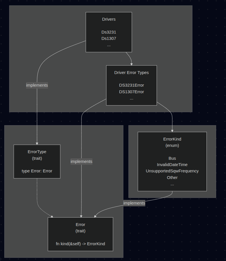
Implementation Example
Here's how the error handling architecture will look in practice:
RTC HAL side:
We define common error kinds and traits that all RTC drivers must implement
#![allow(unused)]
fn main() {
pub enum ErrorKind{
    ...
}

pub trait Error {
    fn kind(&self) -> ErrorKind;
}

pub trait ErrorType {
    /// Error type
    type Error: Error;
}
...
}
Driver side:
Each driver defines its own specific errors but maps them to standard error kinds
#![allow(unused)]
fn main() {
pub enum Error{
    ...
}

impl rtc_hal::error::Error for Error
{
    // Map driver-specific errors to standard RTC HAL error kinds
    fn kind(&self) -> rtc_hal::error::ErrorKind {
        match self {
            Error::InvalidAddress => rtc_hal::error::ErrorKind::InvalidAddress,
            Error::InvalidDateTime => rtc_hal::error::ErrorKind::InvalidDateTime,
            ...
        }
    }
}

impl rtc_hal::error::ErrorType for DriverStruct {
    type Error = crate::error::Error;
}
}
Application side:
Applications can handle errors uniformly across different RTC drivers by matching on ErrorKind
#![allow(unused)]
fn main() {
pub struct DemoApp<RTC> {
    rtc: RTC,
}

impl<RTC: Rtc> DemoApp<RTC> {

    pub fn set_datetime(&mut self, dt: &DateTime) {
        if let Err(e) = self.rtc.set_datetime(dt) {
            // Handle errors generically using standard error kinds
            match e.kind() {
                rtc_hal::error::ErrorKind::InvalidDateTime => {
                    error!("Invalid datetime provided");
                }
                rtc_hal::error::ErrorKind::Bus => {
                    error!("RTC communication failed");
                }
                _ => error!("handle other errors..."),
            }
        }
    }
    ...
}
}
This is the only complex part of the rtc-hal ; the rest is fairly simple (at least that's what i think). Take your time to go through it and understand the structure.
Error Module
Now it is time to put the design into action. In this section, we will implement the error module (error.rs).
Error Kind
We will define the ErrorKind enum to specify the types of errors that can happen when working with RTC drivers. It covers the common problems you'll run into when using RTC hardware.
#![allow(unused)]
fn main() {
/// Common categories of errors for RTC drivers
#[derive(Debug, Clone, Copy, PartialEq, Eq)]
#[cfg_attr(feature = "defmt", derive(defmt::Format))]
#[non_exhaustive]
pub enum ErrorKind {
    // Errors related to core traits
    /// Underlying bus error (I2C, SPI, etc.)
    Bus,
    /// Invalid date/time value provided
    InvalidDateTime,

    // Errors related to extended
    /// Invalid alarm configuration
    InvalidAlarmConfig,
    /// The specified square wave frequency is not supported by the RTC
    UnsupportedSqwFrequency,
    /// Invalid register address
    InvalidAddress,
    /// NVRAM address out of bounds
    NvramOutOfBounds,
    /// NVRAM is write protected
    NvramWriteProtected,

    /// Any other error not covered above
    Other,
}
}
We provide optional defmt support for ErrorKind to enable efficient logging in embedded environments. Users can enable this functionality through the "defmt" feature flag.
non_exhaustive attribute
Here, the #[non_exhaustive] attribute tells Rust that this enum might get new variants in the future. When the user match on this enum in the downstream crate (i.e the one depends on the rtc-hal crate), user must include a wildcard pattern (like _ => ...). This way, even if we add new error types later, it won't be breaking change. You can find my detailed explanation of this attribute in my blog post here.
Error Trait
Next, we will define the Error trait that provides a standard interface for all RTC driver errors:
#![allow(unused)]
fn main() {
pub trait Error: core::fmt::Debug {
    /// Map a driver-specific error into a general category
    fn kind(&self) -> ErrorKind;
}
}
This trait serves as a bridge between specific driver implementations and the general error categories. Any RTC driver error must implement this trait, which requires:
-
Debug trait: All errors must implement Debug so they can be formatted for debugging purposes.
-
kind() method: This method maps any driver-specific error into one of the standard ErrorKind categories. This lets higher-level code handle errors in a consistent way, even when different drivers have different internal error types.
ErrorType Trait
The ErrorType trait defines what error type an RTC driver uses:
#![allow(unused)]
fn main() {
pub trait ErrorType {
    type Error: Error;
}
}
This will be the super trait that the Rtc trait will depend on. This trait is simple but important. It lets RTC drivers specify their error type as an associated type. Having both share the name "Error" might be slightly confusing. Basically, it's telling us that the associated type "Error" must implement the "Error" trait we defined earlier.
Blanket Implementation
We implement a blanket implementation for mutable references:
#![allow(unused)]
fn main() {
impl<T: ErrorType + ?Sized> ErrorType for &mut T {
    type Error = T::Error;
}
}
This allows the driver to not need different code for taking ownership vs reference (or they don't have to pick one), they can write general code. Users can pass either ownership or a reference. For a deeper explanation, check out this blog post here.
Why Use ErrorType?
This pattern separates error type definition from actual functionality. Currently this separation won't be much helpful, because only the Rtc trait depends on it and all other traits depend on Rtc. However, if we plan to add an async version (or some other variant) of Rtc, we won't need to repeat the ErrorType part. This is how embedded-hal has also created the ErrorType trait, so that it can be used in the embedded-hal-async version as well.
Using ErrorKind Directly
If the driver has only the errors we defined in ErrorKind (no custom error kinds), we will give flexibility of using the ErrorKind enum itself directly as the Error. To achieve that, we will need to implement the Error trait for ErrorKind as well.
#![allow(unused)]
fn main() {
impl Error for ErrorKind {
    #[inline]
    fn kind(&self) -> ErrorKind {
        *self
    }
}
}
This implementation allows simple drivers to declare:
#![allow(unused)]
fn main() {
type Error = ErrorKind;
}
The kind() method returns the enum variant itself, since ErrorKind already represents the error category. The #[inline] attribute tells the compiler to optimize this away since it's just returning the same value.
We implement the Display trait also for the ErrorKind:
#![allow(unused)]
fn main() {
impl core::fmt::Display for ErrorKind {
    fn fmt(&self, f: &mut core::fmt::Formatter<'_>) -> core::fmt::Result {
        match self {
            Self::Bus => write!(f, "Underlying bus error occurred"),
            Self::InvalidDateTime => write!(f, "Invalid datetime value provided"),
            Self::InvalidAlarmConfig => write!(f, "Invalid alarm configuration"),
            Self::UnsupportedSqwFrequency => write!(
                f,
                "The specified square wave frequency is not supported by the RTC"
            ),
            Self::InvalidAddress => write!(f, "Invalid register address"),
            Self::NvramOutOfBounds => write!(f, "NVRAM address out of bounds"),
            Self::NvramWriteProtected => write!(f, "NVRAM is write protected"),
            Self::Other => write!(
                f,
                "A different error occurred. The original error may contain more information"
            ),
        }
    }
}
}
The final code (with test):
#![allow(unused)]
fn main() {
//! # RTC Error Types and Classification
//!
//! This module provides a standardized error handling framework for RTC drivers,
//! allowing consistent error categorization across different RTC hardware implementations.

/// Common categories of errors for RTC drivers
#[derive(Debug, Clone, Copy, PartialEq, Eq)]
#[cfg_attr(feature = "defmt", derive(defmt::Format))]
#[non_exhaustive]
pub enum ErrorKind {
    // Errors related to core traits
    /// Underlying bus error (I2C, SPI, etc.)
    Bus,
    /// Invalid date/time value provided
    InvalidDateTime,

    // Errors related to extended
    /// Invalid alarm configuration
    InvalidAlarmConfig,
    /// The specified square wave frequency is not supported by the RTC
    UnsupportedSqwFrequency,
    /// Invalid register address
    InvalidAddress,
    /// NVRAM address out of bounds
    NvramOutOfBounds,
    /// NVRAM is write protected
    NvramWriteProtected,

    /// Any other error not covered above
    Other,
}

/// Trait that RTC driver error types should implement.
///
/// Allows converting driver-specific errors into standard categories.
/// Drivers can either define custom error types or use `ErrorKind` directly.
pub trait Error: core::fmt::Debug {
    /// Map a driver-specific error into a general category
    fn kind(&self) -> ErrorKind;
}

/// RTC error type trait.
///
/// This just defines the error type, to be used by the other traits.
pub trait ErrorType {
    /// Error type
    type Error: Error;
}

/// Allows `ErrorKind` to be used directly as an error type.
///
/// Simple drivers can use `type Error = ErrorKind` instead of defining custom errors.
impl Error for ErrorKind {
    #[inline]
    fn kind(&self) -> ErrorKind {
        *self
    }
}

// blanket impl for all `&mut T`
impl<T: ErrorType + ?Sized> ErrorType for &mut T {
    type Error = T::Error;
}

impl core::fmt::Display for ErrorKind {
    fn fmt(&self, f: &mut core::fmt::Formatter<'_>) -> core::fmt::Result {
        match self {
            Self::Bus => write!(f, "Underlying bus error occurred"),
            Self::InvalidDateTime => write!(f, "Invalid datetime value provided"),
            Self::InvalidAlarmConfig => write!(f, "Invalid alarm configuration"),
            Self::UnsupportedSqwFrequency => write!(
                f,
                "The specified square wave frequency is not supported by the RTC"
            ),
            Self::InvalidAddress => write!(f, "Invalid register address"),
            Self::NvramOutOfBounds => write!(f, "NVRAM address out of bounds"),
            Self::NvramWriteProtected => write!(f, "NVRAM is write protected"),
            Self::Other => write!(
                f,
                "A different error occurred. The original error may contain more information"
            ),
        }
    }
}

#[cfg(test)]
mod tests {
    use super::*;

    // Mock error type for testing
    #[derive(Debug, Clone, Copy, PartialEq, Eq)]
    enum MockRtcError {
        I2cError,
        InvalidDateTime,
        InvalidAlarmTime,
        UnsupportedSqwFrequency,
        InvalidRegisterAddress,
        NvramAddressOutOfBounds,
        NvramWriteProtected,
        UnknownError,
    }

    impl Error for MockRtcError {
        fn kind(&self) -> ErrorKind {
            match self {
                MockRtcError::I2cError => ErrorKind::Bus,
                MockRtcError::InvalidDateTime => ErrorKind::InvalidDateTime,
                MockRtcError::InvalidAlarmTime => ErrorKind::InvalidAlarmConfig,
                MockRtcError::UnsupportedSqwFrequency => ErrorKind::UnsupportedSqwFrequency,
                MockRtcError::InvalidRegisterAddress => ErrorKind::InvalidAddress,
                MockRtcError::NvramAddressOutOfBounds => ErrorKind::NvramOutOfBounds,
                MockRtcError::NvramWriteProtected => ErrorKind::NvramWriteProtected,
                _ => ErrorKind::Other,
            }
        }
    }

    #[test]
    fn test_error_kind_mapping() {
        assert_eq!(MockRtcError::I2cError.kind(), ErrorKind::Bus);
        assert_eq!(
            MockRtcError::InvalidDateTime.kind(),
            ErrorKind::InvalidDateTime
        );
        assert_eq!(
            MockRtcError::InvalidAlarmTime.kind(),
            ErrorKind::InvalidAlarmConfig
        );
        assert_eq!(
            MockRtcError::UnsupportedSqwFrequency.kind(),
            ErrorKind::UnsupportedSqwFrequency
        );
        assert_eq!(
            MockRtcError::InvalidRegisterAddress.kind(),
            ErrorKind::InvalidAddress
        );
        assert_eq!(
            MockRtcError::NvramAddressOutOfBounds.kind(),
            ErrorKind::NvramOutOfBounds
        );
        assert_eq!(
            MockRtcError::NvramWriteProtected.kind(),
            ErrorKind::NvramWriteProtected
        );
        assert_eq!(MockRtcError::UnknownError.kind(), ErrorKind::Other);
    }

    #[test]
    fn test_error_kind_equality() {
        assert_eq!(ErrorKind::Bus, ErrorKind::Bus);
        assert_ne!(ErrorKind::Bus, ErrorKind::InvalidDateTime);
        assert_ne!(
            ErrorKind::InvalidAlarmConfig,
            ErrorKind::UnsupportedSqwFrequency
        );
        assert_ne!(ErrorKind::NvramOutOfBounds, ErrorKind::NvramWriteProtected);
    }

    #[test]
    fn test_error_kind_returns_self() {
        let error = ErrorKind::Other;
        assert_eq!(error.kind(), ErrorKind::Other);
    }

    #[test]
    fn test_error_kind_display_messages() {
        assert_eq!(
            format!("{}", ErrorKind::Bus),
            "Underlying bus error occurred"
        );

        assert_eq!(
            format!("{}", ErrorKind::InvalidDateTime),
            "Invalid datetime value provided"
        );

        assert_eq!(
            format!("{}", ErrorKind::InvalidAlarmConfig),
            "Invalid alarm configuration"
        );

        assert_eq!(
            format!("{}", ErrorKind::UnsupportedSqwFrequency),
            "The specified square wave frequency is not supported by the RTC"
        );

        assert_eq!(
            format!("{}", ErrorKind::InvalidAddress),
            "Invalid register address"
        );

        assert_eq!(
            format!("{}", ErrorKind::NvramOutOfBounds),
            "NVRAM address out of bounds"
        );

        assert_eq!(
            format!("{}", ErrorKind::NvramWriteProtected),
            "NVRAM is write protected"
        );

        assert_eq!(
            format!("{}", ErrorKind::Other),
            "A different error occurred. The original error may contain more information"
        );
    }
}
}
Core Traits
With our error handling foundation in place, we can now implement the core "Rtc" trait that defines the essential RTC operations:
#![allow(unused)]
fn main() {
pub trait Rtc: ErrorType {
    fn get_datetime(&mut self) -> Result<DateTime, Self::Error>;
    fn set_datetime(&mut self, datetime: &DateTime) -> Result<(), Self::Error>;
}
}
We will define two fundamental functions for RTC interaction:
-
get_datetime() - Reads the current date and time from the RTC hardware and converts it into our standardized DateTime struct. The driver handles the hardware-specific details of reading registers and converting between different data formats (like BCD to binary).
-
set_datetime() - Accepts a DateTime instance and writes it to the RTC hardware. The driver is responsible for converting the DateTime into the appropriate hardware format and performing the necessary register writes.
We will shortly define The DateTime struct in the datetime module
Both functions return Result types using Self::Error as the error type. Since Rtc extends the supertrait ErrorType, any driver implementing Rtc must also implement ErrorType and define their associated error type. This creates a unified error handling system where all RTC operations use consistent error categorization through our Error trait.
Blanket Implementation for Rtc Trait
We provide a blanket implementation for mutable references to any type that implements Rtc:
#![allow(unused)]
fn main() {
impl<T: Rtc + ?Sized> Rtc for &mut T {
    #[inline]
    fn get_datetime(&mut self) -> Result<DateTime, Self::Error> {
        T::get_datetime(self)
    }

    #[inline]
    fn set_datetime(&mut self, datetime: &DateTime) -> Result<(), Self::Error> {
        T::set_datetime(self, datetime)
    }
}
}
This implementation allows users to pass either owned RTC instances or mutable references to functions that accept Rtc implementations. The ?Sized bound enables this to work with trait objects and other dynamically sized types.
How Application and Library Developers Use This
Application and library developers who use RTC drivers should take the Rtc instance as an argument to new() and store it in their struct. They should not take &mut Rtc - the trait has a blanket implementation for all &mut T, so taking just Rtc ensures users can still pass a &mut but are not forced to:
#![allow(unused)]
fn main() {
// Correct pattern
pub fn new(rtc: RTC) -> Self {
    Self { rtc }
}

// Avoid this - Forces users to pass mutable references
pub fn new(rtc: &mut Rtc) -> Self {
    Self { rtc }
}
}
This approach provides better flexibility. Users can pass either owned RTC driver instances or mutable references, giving them the choice of ownership model that works best for their use case.
The final code for the rtc module
#![allow(unused)]
fn main() {
//! # RTC Trait Interface
//!
//! This module defines the core trait for Real-Time Clock (RTC) devices in embedded systems.
//!
//! ## Features
//! - Provides a platform-independent interface for reading and writing date/time values to hardware RTC chips.
//! - Compatible with the design patterns of `embedded-hal`, focusing on trait-based abstraction.
//! - Uses the hardware-agnostic `DateTime` struct for representing calendar date and time.
//!
//! ## Usage Notes
//! - Each RTC driver should implement its own error type conforming to the `Error` trait, allowing accurate hardware-specific error reporting.
//! - Drivers are responsible for validating that all `DateTime` values provided are within the supported range of their underlying hardware (for example, some chips only support years 2000-2099).
//! - This trait is intended for use in platform implementors and applications needing unified RTC access across hardware targets.
//!
//! ## For application and library developers
//!
//! Applications and libraries should take the `Rtc` instance as an argument to `new()`, and store it in their
//! struct. They **should not** take `&mut Rtc`, the trait has a blanket impl for all `&mut T`
//! so taking just `Rtc` ensures the user can still pass a `&mut`, but is not forced to.
//!
//! Applications and libraries **should not** try to enable sharing by taking `&mut Rtc` at every method.
//! This is much less ergonomic than owning the `Rtc`, which still allows the user to pass an
//! implementation that does sharing behind the scenes.
//!
//! ## Example
//! ```ignore
//! use crate::{datetime::DateTime, error::ErrorType, rtc::Rtc};
//!
//! let mut rtc = Ds1307::new(i2c);
//! let now = rtc.get_datetime()?;
//! rtc.set_datetime(&DateTime::new(2024, 8, 16, 12, 0, 0)?)?;
//! ```
use crate::{datetime::DateTime, error::ErrorType};

/// Core trait for Real-Time Clock (RTC) devices.
///
/// This trait provides a platform-agnostic interface for reading and
/// writing date/time values from hardware RTC chips. It is designed
/// to be similar in style to `embedded-hal` traits.
///
/// Each RTC implementation should define:
/// - An associated error type for hardware-specific errors
///
/// The `DateTime` struct used here is hardware-agnostic. Drivers must
/// validate that provided values fall within the supported range.
///
/// # Example
///
/// ```ignore
/// let mut rtc = Ds1307::new(i2c);
/// let now = rtc.get_datetime()?;
/// rtc.set_datetime(&DateTime::new(2024, 8, 16, 12, 0, 0)?)?;
pub trait Rtc: ErrorType {
    /// Get the current date and time atomically.
    ///
    /// # Errors
    ///
    /// Returns `Self::Error` if communication with the RTC fails.
    fn get_datetime(&mut self) -> Result<DateTime, Self::Error>;

    /// Set the current date and time atomically.
    ///
    /// # Errors
    ///
    /// Returns `Self::Error` if communication with the RTC fails or
    /// if the provided `DateTime` is out of range for this device.
    fn set_datetime(&mut self, datetime: &DateTime) -> Result<(), Self::Error>;
}

/// blanket impl for all `&mut T`
impl<T: Rtc + ?Sized> Rtc for &mut T {
    #[inline]
    fn get_datetime(&mut self) -> Result<DateTime, Self::Error> {
        T::get_datetime(self)
    }

    #[inline]
    fn set_datetime(&mut self, datetime: &DateTime) -> Result<(), Self::Error> {
        T::set_datetime(self, datetime)
    }
}
}
DateTime module (datetime.rs)
The DateTime module provides a simple date and time struct for RTC drivers. It stores year, month, day, hour, minute, and second values with built-in validation to prevent invalid dates. I won't go through this module step by step since it's pretty straightforward - just basic validation and getters/setters with nothing particularly complex happening here. I want you to go through the code once and understand before proceeding.
The main DateTime struct has private fields to force validation through the new() constructor. This ensures you can't create invalid dates like February 30th or hours greater than 23. The validation checks leap years, days per month, and all time component ranges.
The module supports years from 1970 onwards, which works with most RTC chips. Individual drivers can add stricter limits if their hardware has a smaller range (like DS1307 which only supports 2000-2099).
The struct provides getter methods for all fields and setter methods that re-validate when you change values. For example, if you try to change January 31st to February, it will fail validation and keep the original date unchanged.
Additional features include weekday calculation using a standard algorithm, leap year detection, and utility functions for days in each month. The Weekday enum uses Sunday=1 to Saturday=7 numbering, which drivers can convert if their hardware uses different numbering.
#![allow(unused)]
fn main() {
//! # DateTime Module
//!
//! This module defines a `DateTime` struct and helper functions for representing,
//! validating, and working with calendar date and time values in embedded systems.
//!
//! ## Features
//! - Stores year, month, day, hour, minute, second
//! - Built-in validation for all fields (including leap years and month lengths)
//! - Setter and getter methods that enforce validity
//! - Utility functions for leap year detection, days in a month, and weekday calculation
//!
//! ## Year Range
//! The default supported range is **year >= 1970**, which covers the widest set of
//! popular RTC chips. For example:
//!
//! - DS1307, DS3231: 2000-2099
//!
//! Drivers are responsible for checking and enforcing the *exact* year range of the
//! underlying hardware. The `DateTime` type itself only enforces the lower bound (1970)
//! to remain reusable in contexts outside RTCs.
//!
//! ## Weekday Format
//! - This module uses **1=Sunday to 7=Saturday**
//! - Drivers must handle conversion if required

/// Errors that can occur when working with DateTime
#[derive(Debug, Clone, Copy, PartialEq, Eq)]
#[cfg_attr(feature = "defmt", derive(defmt::Format))]
pub enum DateTimeError {
    /// Invalid month value
    InvalidMonth,
    /// Invalid day value
    InvalidDay,
    /// Invalid hour value
    InvalidHour,
    /// Invalid minute value
    InvalidMinute,
    /// Invalid second value
    InvalidSecond,
    /// Invalid weekday value
    InvalidWeekday,
    /// Invalid Year value
    InvalidYear,
}

impl core::fmt::Display for DateTimeError {
    fn fmt(&self, f: &mut core::fmt::Formatter<'_>) -> core::fmt::Result {
        match self {
            DateTimeError::InvalidMonth => write!(f, "invalid month"),
            DateTimeError::InvalidDay => write!(f, "invalid day"),
            DateTimeError::InvalidHour => write!(f, "invalid hour"),
            DateTimeError::InvalidMinute => write!(f, "invalid minute"),
            DateTimeError::InvalidSecond => write!(f, "invalid second"),
            DateTimeError::InvalidWeekday => write!(f, "invalid weekday"),
            DateTimeError::InvalidYear => write!(f, "invalid year"),
        }
    }
}

impl core::error::Error for DateTimeError {}

/// Date and time representation used across RTC drivers.
///
/// This type represents calendar date and time in a general-purpose way,
/// independent of any specific RTC hardware.
///
/// - Validates that `year >= 1970`
/// - Other limits (e.g., 2000-2099) must be enforced by individual drivers
#[derive(Debug, Clone, Copy, PartialEq, Eq)]
pub struct DateTime {
    /// Year (full year, e.g., 2024)
    year: u16,
    /// Month (1-12)
    month: u8,
    /// Day of the month (1-31 depending on month/year)
    day_of_month: u8,
    /// Hour (0-23)
    hour: u8,
    /// Minute (0-59)
    minute: u8,
    /// Second (0-59)
    second: u8,
}

impl DateTime {
    /// Create a new `DateTime` instance with validation.
    ///
    /// # Errors
    ///
    /// Returns a `DateTimeError` if any component is out of valid range.
    pub fn new(
        year: u16,
        month: u8,
        day_of_month: u8,
        hour: u8,
        minute: u8,
        second: u8,
    ) -> Result<Self, DateTimeError> {
        let dt = DateTime {
            year,
            month,
            day_of_month,
            hour,
            minute,
            second,
        };
        dt.validate()?;
        Ok(dt)
    }

    /// Validate all datetime components.
    ///
    /// # Errors
    ///
    /// Returns the first `DateTimeError` encountered.
    pub fn validate(&self) -> Result<(), DateTimeError> {
        Self::validate_year(self.year)?;
        Self::validate_month(self.month)?;
        Self::validate_day(self.year, self.month, self.day_of_month)?;
        Self::validate_hour(self.hour)?;
        Self::validate_minute(self.minute)?;
        Self::validate_second(self.second)?;
        Ok(())
    }

    /// Validate the year (must be >= 1970).
    fn validate_year(year: u16) -> Result<(), DateTimeError> {
        if year < 1970 {
            return Err(DateTimeError::InvalidYear);
        }
        Ok(())
    }

    /// Validate the month (must be 1-12).
    fn validate_month(month: u8) -> Result<(), DateTimeError> {
        if month == 0 || month > 12 {
            return Err(DateTimeError::InvalidMonth);
        }
        Ok(())
    }

    /// Validate the day (must be within the valid range for the month/year).
    fn validate_day(year: u16, month: u8, day: u8) -> Result<(), DateTimeError> {
        let max_day = days_in_month(year, month);
        if day == 0 || day > max_day {
            return Err(DateTimeError::InvalidDay);
        }
        Ok(())
    }

    /// Validate the hour (must be 0-23).
    fn validate_hour(hour: u8) -> Result<(), DateTimeError> {
        if hour > 23 {
            return Err(DateTimeError::InvalidHour);
        }
        Ok(())
    }

    /// Validate the minute (must be 0-59).
    fn validate_minute(minute: u8) -> Result<(), DateTimeError> {
        if minute > 59 {
            return Err(DateTimeError::InvalidMinute);
        }
        Ok(())
    }

    /// Validate the second (must be 0-59).
    fn validate_second(second: u8) -> Result<(), DateTimeError> {
        if second > 59 {
            return Err(DateTimeError::InvalidSecond);
        }
        Ok(())
    }

    /// Get the year (e.g. 2025).
    pub fn year(&self) -> u16 {
        self.year
    }

    /// Get the month number (1-12).
    pub fn month(&self) -> u8 {
        self.month
    }

    /// Get the day of the month (1-31).
    pub fn day_of_month(&self) -> u8 {
        self.day_of_month
    }

    /// Get the hour (0-23).
    pub fn hour(&self) -> u8 {
        self.hour
    }

    /// Get the minute (0-59).
    pub fn minute(&self) -> u8 {
        self.minute
    }

    /// Get the second (0-59).
    pub fn second(&self) -> u8 {
        self.second
    }

    /// Set year with validation.
    ///
    /// Re-validates the day in case of leap-year or February issues.
    pub fn set_year(&mut self, year: u16) -> Result<(), DateTimeError> {
        Self::validate_year(year)?;
        Self::validate_day(year, self.month, self.day_of_month)?;
        self.year = year;
        Ok(())
    }

    /// Set month with validation.
    ///
    /// Re-validates the day in case month/day mismatch occurs.
    pub fn set_month(&mut self, month: u8) -> Result<(), DateTimeError> {
        Self::validate_month(month)?;
        Self::validate_day(self.year, month, self.day_of_month)?;
        self.month = month;
        Ok(())
    }

    /// Set day with validation.
    pub fn set_day_of_month(&mut self, day_of_month: u8) -> Result<(), DateTimeError> {
        Self::validate_day(self.year, self.month, day_of_month)?;
        self.day_of_month = day_of_month;
        Ok(())
    }

    /// Set hour with validation.
    pub fn set_hour(&mut self, hour: u8) -> Result<(), DateTimeError> {
        Self::validate_hour(hour)?;
        self.hour = hour;
        Ok(())
    }

    /// Set minute with validation.
    pub fn set_minute(&mut self, minute: u8) -> Result<(), DateTimeError> {
        Self::validate_minute(minute)?;
        self.minute = minute;
        Ok(())
    }

    /// Set second with validation.
    pub fn set_second(&mut self, second: u8) -> Result<(), DateTimeError> {
        Self::validate_second(second)?;
        self.second = second;
        Ok(())
    }

    /// Calculate weekday for this DateTime
    pub fn calculate_weekday(&self) -> Result<Weekday, DateTimeError> {
        calculate_weekday(self.year, self.month, self.day_of_month)
    }
}

/// Day of the week (1 = Sunday .. 7 = Saturday)
#[derive(Debug, Clone, Copy, PartialEq, Eq)]
#[repr(u8)]
pub enum Weekday {
    /// Sunday starts with 1
    Sunday = 1,
    /// Monday
    Monday = 2,
    /// Tuesday
    Tuesday = 3,
    /// Wednesday
    Wednesday = 4,
    /// Thursday
    Thursday = 5,
    /// Friday
    Friday = 6,
    /// Saturday
    Saturday = 7,
}

impl Weekday {
    /// Create a Weekday from a raw u8 (1 = Sunday .. 7 = Saturday).
    pub fn from_number(n: u8) -> Result<Self, DateTimeError> {
        match n {
            1 => Ok(Self::Sunday),
            2 => Ok(Self::Monday),
            3 => Ok(Self::Tuesday),
            4 => Ok(Self::Wednesday),
            5 => Ok(Self::Thursday),
            6 => Ok(Self::Friday),
            7 => Ok(Self::Saturday),
            _ => Err(DateTimeError::InvalidWeekday),
        }
    }

    /// Get the number form (1 = Sunday .. 7 = Saturday).
    pub fn to_number(self) -> u8 {
        self as u8
    }

    /// Get the weekday name as a string slice
    pub fn as_str(&self) -> &'static str {
        match self {
            Weekday::Sunday => "Sunday",
            Weekday::Monday => "Monday",
            Weekday::Tuesday => "Tuesday",
            Weekday::Wednesday => "Wednesday",
            Weekday::Thursday => "Thursday",
            Weekday::Friday => "Friday",
            Weekday::Saturday => "Saturday",
        }
    }
}

/// Check if a year is a leap year
pub fn is_leap_year(year: u16) -> bool {
    (year % 4 == 0) && (year % 100 != 0 || year % 400 == 0)
}

/// Get the number of days in a month
pub fn days_in_month(year: u16, month: u8) -> u8 {
    match month {
        1 | 3 | 5 | 7 | 8 | 10 | 12 => 31,
        4 | 6 | 9 | 11 => 30,
        2 => {
            if is_leap_year(year) {
                29
            } else {
                28
            }
        }
        _ => 0,
    }
}

/// Calculate the day of the week using Zeller's congruence algorithm
/// Returns 1=Sunday, 2=Monday, ..., 7=Saturday
pub fn calculate_weekday(year: u16, month: u8, day_of_month: u8) -> Result<Weekday, DateTimeError> {
    let (year, month) = if month < 3 {
        (year - 1, month + 12)
    } else {
        (year, month)
    };

    let k = year % 100;
    let j = year / 100;

    let h =
        (day_of_month as u16 + ((13 * (month as u16 + 1)) / 5) + k + (k / 4) + (j / 4) - 2 * j) % 7;

    // Convert Zeller's result (0=Saturday) to our format (1=Sunday)
    let weekday_num = ((h + 6) % 7) + 1;

    // This should never fail since we're calculating a valid weekday
    Weekday::from_number(weekday_num as u8)
}

#[cfg(test)]
mod tests {
    use super::*;

    #[test]
    fn test_valid_datetime_creation() {
        let dt = DateTime::new(2024, 3, 15, 14, 30, 45).unwrap();
        assert_eq!(dt.year(), 2024);
        assert_eq!(dt.month(), 3);
        assert_eq!(dt.day_of_month(), 15);
        assert_eq!(dt.hour(), 14);
        assert_eq!(dt.minute(), 30);
        assert_eq!(dt.second(), 45);
    }

    #[test]
    fn test_invalid_year() {
        let result = DateTime::new(1969, 1, 1, 0, 0, 0);
        assert_eq!(result.unwrap_err(), DateTimeError::InvalidYear);
    }

    #[test]
    fn test_invalid_month() {
        assert_eq!(
            DateTime::new(2024, 0, 1, 0, 0, 0).unwrap_err(),
            DateTimeError::InvalidMonth
        );
        assert_eq!(
            DateTime::new(2024, 13, 1, 0, 0, 0).unwrap_err(),
            DateTimeError::InvalidMonth
        );
    }

    #[test]
    fn test_invalid_day() {
        // Test February 30th (invalid)
        assert_eq!(
            DateTime::new(2024, 2, 30, 0, 0, 0).unwrap_err(),
            DateTimeError::InvalidDay
        );

        // Test day 0
        assert_eq!(
            DateTime::new(2024, 1, 0, 0, 0, 0).unwrap_err(),
            DateTimeError::InvalidDay
        );

        // Test April 31st (invalid - April has 30 days)
        assert_eq!(
            DateTime::new(2024, 4, 31, 0, 0, 0).unwrap_err(),
            DateTimeError::InvalidDay
        );
    }

    #[test]
    fn test_invalid_hour() {
        assert_eq!(
            DateTime::new(2024, 1, 1, 24, 0, 0).unwrap_err(),
            DateTimeError::InvalidHour
        );
    }

    #[test]
    fn test_invalid_minute() {
        assert_eq!(
            DateTime::new(2024, 1, 1, 0, 60, 0).unwrap_err(),
            DateTimeError::InvalidMinute
        );
    }

    #[test]
    fn test_invalid_second() {
        assert_eq!(
            DateTime::new(2024, 1, 1, 0, 0, 60).unwrap_err(),
            DateTimeError::InvalidSecond
        );
    }

    #[test]
    fn test_leap_year_february_29() {
        // 2024 is a leap year - February 29th should be valid
        assert!(DateTime::new(2024, 2, 29, 0, 0, 0).is_ok());

        // 2023 is not a leap year - February 29th should be invalid
        assert_eq!(
            DateTime::new(2023, 2, 29, 0, 0, 0).unwrap_err(),
            DateTimeError::InvalidDay
        );
    }

    #[test]
    fn test_setters_with_validation() {
        let mut dt = DateTime::new(2024, 1, 1, 0, 0, 0).unwrap();

        // Valid operations
        assert!(dt.set_year(2025).is_ok());
        assert_eq!(dt.year(), 2025);

        assert!(dt.set_month(12).is_ok());
        assert_eq!(dt.month(), 12);

        assert!(dt.set_hour(23).is_ok());
        assert_eq!(dt.hour(), 23);

        // Invalid operations
        assert_eq!(dt.set_year(1969), Err(DateTimeError::InvalidYear));
        assert_eq!(dt.set_month(13), Err(DateTimeError::InvalidMonth));
        assert_eq!(dt.set_hour(24), Err(DateTimeError::InvalidHour));
    }

    #[test]
    fn test_leap_year_edge_cases_in_setters() {
        let mut dt = DateTime::new(2024, 2, 29, 0, 0, 0).unwrap(); // Leap year

        // Changing to non-leap year should fail because Feb 29 becomes invalid
        assert_eq!(dt.set_year(2023), Err(DateTimeError::InvalidDay));

        // Original value should remain unchanged after failed operation
        assert_eq!(dt.year(), 2024);
        assert_eq!(dt.day_of_month(), 29);
    }

    #[test]
    fn test_month_day_validation_in_setters() {
        let mut dt = DateTime::new(2024, 1, 31, 0, 0, 0).unwrap(); // January 31st

        // Changing to February should fail because Feb doesn't have 31 days
        assert_eq!(dt.set_month(2), Err(DateTimeError::InvalidDay));

        // Original value should remain unchanged
        assert_eq!(dt.month(), 1);
        assert_eq!(dt.day_of_month(), 31);

        // But changing to March should work (March has 31 days)
        assert!(dt.set_month(3).is_ok());
        assert_eq!(dt.month(), 3);
    }

    #[test]
    fn test_weekday_calculation() {
        let dt = DateTime::new(2024, 1, 1, 0, 0, 0).unwrap(); // New Year 2024
        let weekday = dt.calculate_weekday().unwrap();
        assert_eq!(weekday, Weekday::Monday); // January 1, 2024 was a Monday

        let dt = DateTime::new(2024, 12, 25, 0, 0, 0).unwrap();
        let weekday = dt.calculate_weekday().unwrap();
        assert_eq!(weekday, Weekday::Wednesday); // December 25, 2024 is a Wednesday
    }

    #[test]
    fn test_weekday_from_number() {
        assert_eq!(Weekday::from_number(1).unwrap(), Weekday::Sunday);
        assert_eq!(Weekday::from_number(2).unwrap(), Weekday::Monday);
        assert_eq!(Weekday::from_number(7).unwrap(), Weekday::Saturday);
        assert_eq!(Weekday::from_number(3).unwrap(), Weekday::Tuesday);

        assert_eq!(
            Weekday::from_number(0).unwrap_err(),
            DateTimeError::InvalidWeekday
        );
        assert_eq!(
            Weekday::from_number(8).unwrap_err(),
            DateTimeError::InvalidWeekday
        );
    }

    #[test]
    fn test_weekday_to_number() {
        assert_eq!(Weekday::Sunday.to_number(), 1);
        assert_eq!(Weekday::Monday.to_number(), 2);
        assert_eq!(Weekday::Saturday.to_number(), 7);
    }

    #[test]
    fn test_weekday_as_str() {
        assert_eq!(Weekday::Sunday.as_str(), "Sunday");
        assert_eq!(Weekday::Monday.as_str(), "Monday");
        assert_eq!(Weekday::Tuesday.as_str(), "Tuesday");
        assert_eq!(Weekday::Wednesday.as_str(), "Wednesday");
        assert_eq!(Weekday::Thursday.as_str(), "Thursday");
        assert_eq!(Weekday::Friday.as_str(), "Friday");
        assert_eq!(Weekday::Saturday.as_str(), "Saturday");
    }

    #[test]
    fn test_calculate_weekday_known_dates() {
        // Test some known dates
        assert_eq!(calculate_weekday(2000, 1, 1).unwrap(), Weekday::Saturday);
        assert_eq!(calculate_weekday(2024, 1, 1).unwrap(), Weekday::Monday);
        assert_eq!(calculate_weekday(2025, 8, 15).unwrap(), Weekday::Friday);

        // Test leap year boundary
        assert_eq!(calculate_weekday(2024, 2, 29).unwrap(), Weekday::Thursday); // Leap day 2024
    }

    #[test]
    fn test_is_leap_year() {
        // Regular leap years (divisible by 4)
        assert!(is_leap_year(2024));
        assert!(is_leap_year(2020));
        assert!(is_leap_year(1996));

        // Non-leap years
        assert!(!is_leap_year(2023));
        assert!(!is_leap_year(2021));
        assert!(!is_leap_year(1999));

        // Century years (divisible by 100 but not 400)
        assert!(!is_leap_year(1900));
        assert!(!is_leap_year(2100));

        // Century years divisible by 400
        assert!(is_leap_year(2000));
        assert!(is_leap_year(1600));
    }

    #[test]
    fn test_days_in_month() {
        // January (31 days)
        assert_eq!(days_in_month(2024, 1), 31);

        // February leap year (29 days)
        assert_eq!(days_in_month(2024, 2), 29);

        // February non-leap year (28 days)
        assert_eq!(days_in_month(2023, 2), 28);

        // April (30 days)
        assert_eq!(days_in_month(2024, 4), 30);

        // December (31 days)
        assert_eq!(days_in_month(2024, 12), 31);

        // Invalid month
        assert_eq!(days_in_month(2024, 13), 0);
        assert_eq!(days_in_month(2024, 0), 0);
    }

    #[test]
    fn test_setter_interdependency_edge_cases() {
        // January 31 → February (invalid because Feb max is 28/29)
        let mut dt = DateTime::new(2023, 1, 31, 0, 0, 0).unwrap();
        assert_eq!(dt.set_month(2), Err(DateTimeError::InvalidDay));

        // March 31 → April (invalid because April max is 30)
        let mut dt = DateTime::new(2023, 3, 31, 0, 0, 0).unwrap();
        assert_eq!(dt.set_month(4), Err(DateTimeError::InvalidDay));

        // Leap year Feb 29 → non-leap year
        let mut dt = DateTime::new(2024, 2, 29, 0, 0, 0).unwrap();
        assert_eq!(dt.set_year(2023), Err(DateTimeError::InvalidDay));

        // Non-leap year Feb 28 → leap year (should work)
        let mut dt = DateTime::new(2023, 2, 28, 0, 0, 0).unwrap();
        assert!(dt.set_year(2024).is_ok());
    }

    #[test]
    fn test_display_datetime_error() {
        assert_eq!(format!("{}", DateTimeError::InvalidMonth), "invalid month");
        assert_eq!(format!("{}", DateTimeError::InvalidDay), "invalid day");
        assert_eq!(format!("{}", DateTimeError::InvalidHour), "invalid hour");
        assert_eq!(
            format!("{}", DateTimeError::InvalidMinute),
            "invalid minute"
        );
        assert_eq!(
            format!("{}", DateTimeError::InvalidSecond),
            "invalid second"
        );
        assert_eq!(
            format!("{}", DateTimeError::InvalidWeekday),
            "invalid weekday"
        );
        assert_eq!(format!("{}", DateTimeError::InvalidYear), "invalid year");
    }

    #[test]
    fn test_datetime_error_trait() {
        let error = DateTimeError::InvalidMonth;
        let _: &dyn core::error::Error = &error;
    }

    #[test]
    fn test_boundary_values() {
        // Test minimum valid year
        assert!(DateTime::new(1970, 1, 1, 0, 0, 0).is_ok());

        // Test maximum valid time values
        assert!(DateTime::new(2024, 12, 31, 23, 59, 59).is_ok());

        // Test minimum valid day/month
        assert!(DateTime::new(2024, 1, 1, 0, 0, 0).is_ok());
    }

    #[test]
    fn test_february_edge_cases() {
        // Test February 28 in leap year
        assert!(DateTime::new(2024, 2, 28, 0, 0, 0).is_ok());

        // Test February 28 in non-leap year
        assert!(DateTime::new(2023, 2, 28, 0, 0, 0).is_ok());

        // Test February 29 in non-leap year (should fail)
        assert_eq!(
            DateTime::new(2023, 2, 29, 0, 0, 0).unwrap_err(),
            DateTimeError::InvalidDay
        );
    }

    #[test]
    fn test_all_month_max_days() {
        let year = 2023; // Non-leap year

        // 31-day months
        for month in [1, 3, 5, 7, 8, 10, 12] {
            assert!(DateTime::new(year, month, 31, 0, 0, 0).is_ok());
            assert_eq!(
                DateTime::new(year, month, 32, 0, 0, 0).unwrap_err(),
                DateTimeError::InvalidDay
            );
        }

        // 30-day months
        for month in [4, 6, 9, 11] {
            assert!(DateTime::new(year, month, 30, 0, 0, 0).is_ok());
            assert_eq!(
                DateTime::new(year, month, 31, 0, 0, 0).unwrap_err(),
                DateTimeError::InvalidDay
            );
        }
    }

    #[test]
    fn test_set_day_of_month() {
        let mut dt = DateTime::new(2024, 5, 15, 12, 30, 45).unwrap();

        assert!(dt.set_day_of_month(10).is_ok());
        assert_eq!(dt.day_of_month, 10);
    }

    #[test]
    fn test_all_setters_preserve_state_on_error() {
        let mut dt = DateTime::new(2024, 5, 15, 12, 30, 45).unwrap();
        let original = dt;

        // Test each setter preserves state when error occurs
        assert!(dt.set_day_of_month(40).is_err());
        assert_eq!(dt, original);

        assert!(dt.set_minute(70).is_err());
        assert_eq!(dt, original);

        assert!(dt.set_second(70).is_err());
        assert_eq!(dt, original);
    }

    #[test]
    fn test_set_minute() {
        let mut dt = DateTime::new(2024, 5, 15, 12, 30, 45).unwrap();

        assert!(dt.set_minute(10).is_ok());
        assert_eq!(dt.minute, 10);
    }

    #[test]
    fn test_set_second() {
        let mut dt = DateTime::new(2024, 5, 15, 12, 30, 45).unwrap();
        assert!(dt.set_second(10).is_ok());
        assert_eq!(dt.second, 10);
    }
}
}
Control Trait
This could have been part of the original Rtc trait, but I'm not sure if all RTC hardware supports power control yet. So even though this is basic functionality, I've separated it into its own trait. This trait depends on the Rtc supertrait, which means drivers must always implement the Rtc trait first if they want to use this and other similar traits we'll create later.
The RtcPowerControl trait provides basic power control functionality for RTC devices. The start_clock() function is to start or resume the RTC oscillator so timekeeping can continue, while halt_clock() is to pause the oscillator until it's restarted again.
content of the control.rs file
#![allow(unused)]
fn main() {
//! Power control functionality for RTC devices.

use crate::rtc::Rtc;

/// This trait extends [`Rtc`] with methods to start and halt the RTC clock.
pub trait RtcPowerControl: Rtc {
    /// Start or resume the RTC oscillator so that timekeeping can continue.
    fn start_clock(&mut self) -> Result<(), Self::Error>;

    /// Halt the RTC oscillator, pausing timekeeping until restarted.
    fn halt_clock(&mut self) -> Result<(), Self::Error>;
}
}
Square Wave Trait
Many RTCs support a feature called "square wave" output through a hardware pin. You can set different square wave frequencies like 1Hz, 1024 Hz, 32kHz and so on. The available frequencies depend on the specific RTC chip.
The square wave output is commonly used for generating precise periodic interrupts. For example, you can set the RTC to output a 1Hz signal and use it to interrupt your microcontroller every second for updating displays or performing periodic tasks without constantly polling the RTC.
We will create SquareWaveFreq enum with the standard frequencies supported by most RTC chips. The Custom variant allows drivers to support chip-specific frequencies not covered by the standard options.
#![allow(unused)]
fn main() {
/// Square wave output frequencies
#[derive(Debug, Clone, Copy, PartialEq, Eq)]
pub enum SquareWaveFreq {
    /// 1 Hz
    Hz1,
    /// 1024 Hz (1.024 kHz)
    Hz1024,
    /// 4096 Hz (4.096 kHz)
    Hz4096,
    /// 8192 Hz (8.192 kHz)
    Hz8192,
    /// 32768 Hz (32.768 kHz)
    Hz32768,
    /// Custom frequency (if supported by device)
    Custom(u32),
}
}
Our square wave trait has four methods. The start_square_wave() method sets the frequency and starts the square wave output in one operation. The enable_square_wave() and disable_square_wave() methods allow you to turn the output on and off without changing the frequency. Finally, set_square_wave_frequency() lets you change the frequency without enabling or disabling the output.
#![allow(unused)]
fn main() {
/// Square wave functionality trait
pub trait SquareWave: Rtc {
    /// Configure Frequency and enable square wave
    fn start_square_wave(&mut self, freq: SquareWaveFreq) -> Result<(), Self::Error>;

    /// Enable square wave output
    fn enable_square_wave(&mut self) -> Result<(), Self::Error>;

    /// Disable square wave output
    fn disable_square_wave(&mut self) -> Result<(), Self::Error>;

    /// Set the frequency (without enabling/disabling)
    fn set_square_wave_frequency(&mut self, freq: SquareWaveFreq) -> Result<(), Self::Error>;
}
}
We'll also provide utility methods for the SquareWaveFreq enum. The to_hz() method converts it to the actual frequency value in Hz, while from_hz() converts a Hz value back into the appropriate enum variant.
#![allow(unused)]

fn main() {
impl SquareWaveFreq {
    /// Get frequency value in Hz
    pub fn to_hz(&self) -> u32 {
        match self {
            Self::Hz1 => 1,
            Self::Hz1024 => 1024,
            Self::Hz4096 => 4096,
            Self::Hz8192 => 8192,
            Self::Hz32768 => 32768,
            Self::Custom(freq) => *freq,
        }
    }

    /// Create from Hz value
    pub fn from_hz(hz: u32) -> Self {
        match hz {
            1 => Self::Hz1,
            1024 => Self::Hz1024,
            4096 => Self::Hz4096,
            8192 => Self::Hz8192,
            32768 => Self::Hz32768,
            other => Self::Custom(other),
        }
    }
}
}
The full code for the square_wave.rs module
#![allow(unused)]
fn main() {
//! Traits for Square Wave control

use crate::rtc::Rtc;

/// Square wave output frequencies
#[derive(Debug, Clone, Copy, PartialEq, Eq)]
pub enum SquareWaveFreq {
    /// 1 Hz
    Hz1,
    /// 1024 Hz (1.024 kHz)
    Hz1024,
    /// 4096 Hz (4.096 kHz)
    Hz4096,
    /// 8192 Hz (8.192 kHz)
    Hz8192,
    /// 32768 Hz (32.768 kHz)
    Hz32768,
    /// Custom frequency (if supported by device)
    Custom(u32),
}

impl SquareWaveFreq {
    /// Get frequency value in Hz
    pub fn to_hz(&self) -> u32 {
        match self {
            Self::Hz1 => 1,
            Self::Hz1024 => 1024,
            Self::Hz4096 => 4096,
            Self::Hz8192 => 8192,
            Self::Hz32768 => 32768,
            Self::Custom(freq) => *freq,
        }
    }

    /// Create from Hz value
    pub fn from_hz(hz: u32) -> Self {
        match hz {
            1 => Self::Hz1,
            1024 => Self::Hz1024,
            4096 => Self::Hz4096,
            8192 => Self::Hz8192,
            32768 => Self::Hz32768,
            other => Self::Custom(other),
        }
    }
}

/// Square wave functionality trait
pub trait SquareWave: Rtc {
    /// Configure Frequency and enable square wave
    fn start_square_wave(&mut self, freq: SquareWaveFreq) -> Result<(), Self::Error>;

    /// Enable square wave output
    fn enable_square_wave(&mut self) -> Result<(), Self::Error>;

    /// Disable square wave output
    fn disable_square_wave(&mut self) -> Result<(), Self::Error>;

    /// Set the frequency (without enabling/disabling)
    fn set_square_wave_frequency(&mut self, freq: SquareWaveFreq) -> Result<(), Self::Error>;
}

#[cfg(test)]
mod tests {
    use super::*;

    #[test]
    fn test_to_hz_standard_frequencies() {
        assert_eq!(SquareWaveFreq::Hz1.to_hz(), 1);
        assert_eq!(SquareWaveFreq::Hz1024.to_hz(), 1024);
        assert_eq!(SquareWaveFreq::Hz4096.to_hz(), 4096);
        assert_eq!(SquareWaveFreq::Hz8192.to_hz(), 8192);
        assert_eq!(SquareWaveFreq::Hz32768.to_hz(), 32768);
    }

    #[test]
    fn test_to_hz_custom_frequencies() {
        assert_eq!(SquareWaveFreq::Custom(0).to_hz(), 0);
        assert_eq!(SquareWaveFreq::Custom(100).to_hz(), 100);
        assert_eq!(SquareWaveFreq::Custom(12345).to_hz(), 12345);
        assert_eq!(SquareWaveFreq::Custom(u32::MAX).to_hz(), u32::MAX);
    }

    #[test]
    fn test_from_hz_standard_frequencies() {
        assert_eq!(SquareWaveFreq::from_hz(1), SquareWaveFreq::Hz1);
        assert_eq!(SquareWaveFreq::from_hz(1024), SquareWaveFreq::Hz1024);
        assert_eq!(SquareWaveFreq::from_hz(4096), SquareWaveFreq::Hz4096);
        assert_eq!(SquareWaveFreq::from_hz(8192), SquareWaveFreq::Hz8192);
        assert_eq!(SquareWaveFreq::from_hz(32768), SquareWaveFreq::Hz32768);
    }

    #[test]
    fn test_from_hz_custom_frequencies() {
        assert_eq!(SquareWaveFreq::from_hz(0), SquareWaveFreq::Custom(0));
        assert_eq!(SquareWaveFreq::from_hz(50), SquareWaveFreq::Custom(50));
        assert_eq!(SquareWaveFreq::from_hz(2048), SquareWaveFreq::Custom(2048));
        assert_eq!(SquareWaveFreq::from_hz(9999), SquareWaveFreq::Custom(9999));
        assert_eq!(
            SquareWaveFreq::from_hz(u32::MAX),
            SquareWaveFreq::Custom(u32::MAX)
        );
    }

    #[test]
    fn test_round_trip_conversion() {
        let test_frequencies = vec![
            SquareWaveFreq::Hz1,
            SquareWaveFreq::Hz1024,
            SquareWaveFreq::Hz4096,
            SquareWaveFreq::Hz8192,
            SquareWaveFreq::Hz32768,
            SquareWaveFreq::Custom(0),
            SquareWaveFreq::Custom(42),
            SquareWaveFreq::Custom(2048),
            SquareWaveFreq::Custom(9876),
            SquareWaveFreq::Custom(u32::MAX),
        ];

        for original_freq in test_frequencies {
            let hz_value = original_freq.to_hz();
            let converted_back = SquareWaveFreq::from_hz(hz_value);
            assert_eq!(original_freq, converted_back);
        }
    }

    #[test]
    fn test_frequency_ordering() {
        let frequencies = [
            SquareWaveFreq::Hz1,
            SquareWaveFreq::Hz1024,
            SquareWaveFreq::Hz4096,
            SquareWaveFreq::Hz8192,
            SquareWaveFreq::Hz32768,
        ];

        let hz_values: Vec<u32> = frequencies.iter().map(|f| f.to_hz()).collect();

        for i in 1..hz_values.len() {
            assert!(hz_values[i] > hz_values[i - 1]);
        }
    }

    #[test]
    fn test_custom_frequency_edge_cases() {
        let edge_cases = vec![
            (0, SquareWaveFreq::Custom(0)),
            (2, SquareWaveFreq::Custom(2)),
            (1023, SquareWaveFreq::Custom(1023)),
            (1025, SquareWaveFreq::Custom(1025)),
            (4095, SquareWaveFreq::Custom(4095)),
            (4097, SquareWaveFreq::Custom(4097)),
            (8191, SquareWaveFreq::Custom(8191)),
            (8193, SquareWaveFreq::Custom(8193)),
            (32767, SquareWaveFreq::Custom(32767)),
            (32769, SquareWaveFreq::Custom(32769)),
        ];

        for (hz, expected) in edge_cases {
            assert_eq!(SquareWaveFreq::from_hz(hz), expected);
            assert_eq!(expected.to_hz(), hz);
        }
    }

    #[test]
    fn test_standard_frequencies_are_powers_of_two() {
        assert_eq!(SquareWaveFreq::Hz1024.to_hz(), 1024);
        assert_eq!(SquareWaveFreq::Hz4096.to_hz(), 4096);
        assert_eq!(SquareWaveFreq::Hz8192.to_hz(), 8192);
        assert_eq!(SquareWaveFreq::Hz32768.to_hz(), 32768);

        let freq_1024 = SquareWaveFreq::Hz1024.to_hz();
        let freq_4096 = SquareWaveFreq::Hz4096.to_hz();
        let freq_8192 = SquareWaveFreq::Hz8192.to_hz();
        let freq_32768 = SquareWaveFreq::Hz32768.to_hz();

        assert_eq!(freq_4096, freq_1024 * 4);
        assert_eq!(freq_8192, freq_4096 * 2);
        assert_eq!(freq_32768, freq_8192 * 4);
    }

    #[test]
    fn test_custom_with_standard_values() {
        let custom_1024 = SquareWaveFreq::Custom(1024);
        let custom_4096 = SquareWaveFreq::Custom(4096);

        assert_eq!(custom_1024.to_hz(), 1024);
        assert_eq!(custom_4096.to_hz(), 4096);

        assert_ne!(custom_1024, SquareWaveFreq::Hz1024);
        assert_ne!(custom_4096, SquareWaveFreq::Hz4096);
    }
}
}
Non-volatile memory
Some RTCs include built-in non-volatile memory (NVRAM) for storing user data that persists even when the main power is lost. For example, the DS1307 has 56 bytes of NVRAM, while the DS3231 has none. This memory is separate from the timekeeping registers and can store configuration settings, calibration data, or any application-specific information.
The RtcNvram trait provides a simple interface for reading and writing this memory. It uses byte-level addressing with an offset parameter, allowing you to access any portion of the available NVRAM. The trait also includes a nvram_size() method so applications can determine how much memory is available.
The full code for the nvram.rs module
#![allow(unused)]

fn main() {
/// RTC with non-volatile memory (NVRAM/SRAM) access
pub trait RtcNvram: Rtc {
    /// Read data from NVRAM starting at the given offset
    ///
    /// # Parameters
    /// * `offset` - NVRAM offset (0 = first NVRAM byte, up to device-specific max)
    /// * `buffer` - Buffer to store the read data
    ///
    /// # Returns
    /// * `Ok(())` on success
    /// * `Err(Self::Error)` if offset or length is invalid, or read fails
    fn read_nvram(&mut self, offset: u8, buffer: &mut [u8]) -> Result<(), Self::Error>;

    /// Write data to NVRAM starting at the given offset
    ///
    /// # Parameters
    /// * `offset` - NVRAM offset (0 = first NVRAM byte, up to device-specific max)
    /// * `data` - Data to write to NVRAM
    ///
    /// # Returns
    /// * `Ok(())` on success
    /// * `Err(Self::Error)` if offset or length is invalid, or write fails
    fn write_nvram(&mut self, offset: u8, data: &[u8]) -> Result<(), Self::Error>;

    /// Get the size of available NVRAM in bytes
    ///
    /// # Returns
    /// Total NVRAM size (e.g., 56 for DS1307, 0 for DS3231)
    fn nvram_size(&self) -> u16;
}
}
Binary Coded Decimal(BCD) utilities
We won't declare any traits here - instead we'll provide utility functions for BCD operations. Most RTC chips use BCD format to store time and date values.
Binary Code Decimal(BCD)
If I ask you the value of binary "00010010", you will do the usual math (or use a programmer calculator) and say it is 18 in decimal (or 0x12 in hex). But in BCD format, this same binary represents decimal 12, not 18!
Don't let hex looking same as BCD fool you, there is a difference. Let me show you.
How BCD Works
BCD uses 4 bits for each decimal digit. So if you want to show decimal 12, you split it into two digits (1 and 2) and convert each one separately.
Decimal:    1    2
BCD:     0001 0010
Bits:    8421 8421
To read this:
First 4 bits (0001) = 1 Second 4 bits (0010) = 2
Here, the first part represents the tens of a number. So we have to multiply it by 10. The second part represents the ones of a number
Put together: (1 × 10) + (2 * 1) = 12
Let's do another example to make it clear. Here is how decimal 36 represented as
Decimal:    3    6
BCD:     0011 0110
Bits:    8421 8421
To read this:
First 4 bits (0011) = 3 Second 4 bits (0110) = 6
Put together: (3 × 10) + 6 = 36
BCD vs Hex
Here's the tricky part. The binary 0011 0110 looks like hex 0x36 (which is decimal 54). But in BCD, it means decimal 36.
The big difference: BCD only allows 0-9 in each 4-bit group.
Hex can go from 0-15 (shown as 0-9, A-F), but BCD stops at 9. This makes sense because each 4-bit group represents one decimal digit, and single digits only go 0 to 9.
What Happens When You Break the Rules
Binary:  0011 1010
Hex:     0x3A (decimal 58)
BCD:     Not valid!
This doesn't work in BCD because the second group (1010) is 10, which isn't a single digit. Hex is fine with this (0x3A), but BCD says no.
BCD simplifies displaying decimal numbers (for example, on a 7-segment display driven by a MAX7219). Each 4-bit group directly represents a single decimal digit.
DS1307
One of the RTC chips for which we will first implement the RTC HAL is the DS1307. The DS1307 keeps track of seconds, minutes, hours, day of the week, date of the month, month, and year with leap-year compensation valid up to the year 2100. The device automatically adjusts the end-of-month date for months with fewer than 31 days, including leap-year corrections.
According to the datasheet, it includes 56 bytes nonvolatile RAM for data storage. It consumes less than 500 nA in battery backup mode with the oscillator running.
The DS1307 supports both 24-hour and 12-hour time formats with an AM/PM indicator. A built-in power-sense circuit capable of detecting power failures and automatically switches to a backup battery, allowing timekeeping to continue without interruption.
Module
The DS1307 is available in two package types: an 8-pin DIP, which is larger and breadboard-friendly, and an 8-pin SOIC, which is smaller and intended for soldering onto circuit boards. You can buy just the chip or a complete RTC module that includes the DS1307, an external memory chip such as the AT24C32, and a battery holder so it can keep time even when power is removed.
I purchased an HW-111 RTC module, which is one of the common options. Another popular choice is the Tiny RTC module. These modules include the DS1307 IC, an AT24C32 EEPROM for extra storage, and a 32.768 kHz crystal for accurate timekeeping.
DS1307 Module Pinout
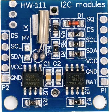
The DS1307 module has two identical rows of pins labeled P1 (right side) and P2 (left side). Pins with the same name are internally connected, so we can use either side. This is especially useful when daisy-chaining modules.
- SQ - Square Wave output pin. It can be configured to generate a steady square wave at selectable frequencies of 1 Hz, 4 kHz, 8 kHz, or 32 kHz. This is useful in projects that require a consistent timed pulse.
- DS - Optional temperature sensor output. If the module includes a DS18B20 temperature sensor mounted near the battery holder (labeled U1), this pin will output temperature data.
- SCL - Serial Clock line for the I2C interface. It synchronizes data transfer between the DS1307 and the microcontroller.
- SDA - Serial Data line for the I2C interface. It is used for bidirectional data transfer.
- VCC - Power supply input for the module. The operating voltage is typically 3.3 V to 5.5 V.
- GND - Ground connection.
- BAT - a backup supply input for a standard 3V lithium cell or other energy source, ensuring accurate timekeeping when the main power is interrupted.
I2C Interface
We can use the I2C protocol to communicate between the module and a microcontroller. Both the DS1307 RTC chip and the onboard 24C32 EEPROM share the same I2C bus. Each device has its own fixed address so the microcontroller can tell them apart. The DS1307 uses address 0x68, while the 24C32 uses address 0x50. We will not focus on the 24C32 component, at least not in this chapter.
The DS1307 only works with standard I2C speed, which is 100kHz.
DS1307 Registers
The DS1307 contains 7 registers for storing date and time data, one control register, and 56 registers for non-volatile RAM.
When you perform a multibyte read or write, the internal address pointer automatically moves to the next location. If it reaches 3Fh (the last RAM address), it wraps back to 00h, which is the start of the clock registers.
Register Map
Here is the simplified register map table. The datasheet shows one big table with address and all the bit details together. I split it up to make it easier to understand. This first table shows what each register address does. Each register in the DS1307 stores 8 bits of data.
| ADDRESS | FUNCTION |
|---|---|
| 00h | Seconds |
| 01h | Minutes |
| 02h | Hours |
| 03h | Day |
| 04h | Date |
| 05h | Month |
| 06h | Year |
| 07h | Control |
| 08h-3Fh | RAM |
I will explain the calendar-related registers and the control register in depth in the next chapter. For now, we will give a quick overview of the RAM registers.
RAM: 56 bytes of non-volatile storage
The DS1307 gives you 56 bytes of RAM to store your own data. This memory is non-volatile, meaning it retains its contents even when the device is powered down, as long as a backup battery is connected.
The RAM uses addresses 08h to 3Fh (that's 56 locations total). Each location can store one byte of data, from 00h to FFh.
Addresses: 08h, 09h, 0Ah ... 3Eh, 3Fh
Storage:   56 bytes total
Data:      Any value from 00h to FFh
You can store any data you want here - numbers, settings, flags, or small data logs. Unlike the time registers that need special BCD format, RAM accepts any value from 00h to FFh directly.
Example uses
Store user settings like alarm time, temperature readings from sensors, or flags to remember what your device was doing. With a backup battery, your device remembers this data when it starts up again.
Details of Time Data Bits
Now let's look at how the data is stored inside each register. Remember, each register holds 8 bits (bit 7 to bit 0), and the time values are stored in BCD format.
| REGISTER | BIT 7 | BIT 6 | BIT 5 | BIT 4 | BIT 3 | BIT 2 | BIT 1 | BIT 0 |
|---|---|---|---|---|---|---|---|---|
| Seconds | CH | Tens digit of seconds | Ones digit of seconds | |||||
| Minutes | 0 | Tens digit of minutes | Ones digit of minutes | |||||
| Hours | 0 | Select 12/24 format |
PM/AM Flag in 12 hour format or Part of Tens in 24 hour format |
Tens digit of hours | Ones digit of hours | |||
| Day | 0 | 0 | 0 | 0 | 0 | Day value (1-7) | ||
| Date | 0 | 0 | Tens digit of date | Ones digit of date | ||||
| Month | 0 | 0 | 0 | Tens digit of month | Ones digit of month | |||
| Year | Tens digit of year | Ones digit of year | ||||||
Seconds: Range 00-59
The bits 0-3 represent the ones digit part of the seconds. The bits 4-6 represent the tens digit part of the seconds.
If you want to represent seconds 30, the BCD format will be: 0011 0000. So, we will put 011 in bits 4-6 (tens digit) and 0000 in bits 0-3 (ones digit).
Bit:     7 6 5 4 3 2 1 0
Value:   0 0 1 1 0 0 0 0
         │ └─┬─┘ └──┬──┘
         │   3      0
         CH bit
CH bit (bit 7) controls clock halt - it's like an on/off switch for the entire clock (1 = clock stopped, 0 = clock running).
Minutes: Range 00-59
The bits 0-3 represent the ones digit part of the minutes. The bits 4-6 represent the tens digit part of the minutes.
If you want to represent minutes 45, the BCD format will be: 0100 0101. So, we will put 100 in bits 4-6 (tens digit) and 0101 in bits 0-3 (ones digit).
Bit:     7 6 5 4 3 2 1 0
Value:   0 1 0 0 0 1 0 1
         │ └─┬─┘ └──┬──┘
         │   4      5
         Always 0
Bit 7 is always 0.
Hours: Range 1-12 + AM/PM (12-hour mode) or 00-23 (24-hour mode)
In 12-hour mode:
- Bit 6 = 1 (selects 12-hour format)
- Bit 5 = AM/PM bit (0=AM, 1=PM)
- Bit 4 = tens digit of hour (0 or 1)
- Bits 3-0 = ones digit of hour
In 24-hour mode:
- Bit 6 = 0 (selects 24-hour format)
- Bits 5-4 = tens digit of hour
- Bits 3-0 = ones digit of hour
Important: The hours value must be re-entered whenever the 12/24-hour mode bit is changed.
If you want to represent 2 PM in 12-hour mode, the format will be: 0110 0010. So bit 6=1 (12-hour), bit 5=1 (PM), bit 4=0 (tens digit), bits 3-0 will be 0010 (ones digit).
Bit:     7 6 5 4 3 2 1 0
Value:   0 1 1 0 0 0 1 0
         │ │ │ │ └──┬──┘
         │ │ │ │    2
         │ │ │ tens digit
         │ │ PM bit
         │ 12-hour format
         Always 0
If you want to represent 14:00 in 24-hour mode, the format will be: 0001 0100. So bit 6=0 (24-hour), bits 5-4 will be 01 (tens digit), bits 3-0 will be 0100 (ones digit).
Bit:     7 6 5 4 3 2 1 0
Value:   0 0 0 1 0 1 0 0
         │ │ └┬┘ └──┬──┘
         │ │  1     4
         │ 24-hour format
         Always 0
Day: Range 01-07 (1=Sunday, 2=Monday, etc.)
The bits 0-2 represent the day value. Bits 3-7 are always 0.
If you want to represent Tuesday (day 3), the format will be: 0000 0011.
Bit:     7 6 5 4 3 2 1 0
Value:   0 0 0 0 0 0 1 1
         └───┬───┘ └─┬─┘
         Always 0     3
Date: Range 01-31 (day of month)
The bits 0-3 represent the ones digit part of the date. The bits 4-5 represent the tens digit part of the date.
If you want to represent date 25, the BCD format will be: 0010 0101. So, we will put 10 in bits 4-5 (tens digit) and 0101 in bits 0-3 (ones digit).
Bit:     7 6 5 4 3 2 1 0
Value:   0 0 1 0 0 1 0 1
         └┬┘ └┬┘ └──┬──┘
          0   2     5
         Always 0
Bits 6-7 are always 0.
Month: Range 01-12
The bits 0-3 represent the ones digit part of the month. Bit 4 represents the tens digit part of the month.
If you want to represent month 12 (December), the BCD format will be: 0001 0010. So, we will put 1 in bit 4 (tens digit) and 0010 in bits 0-3 (ones digit).
Bit: 7 6 5 4 3 2 1 0
Value: 0 0 0 1 0 0 1 0
└─┬─┘ │ └──┬──┘
Always 0 1 2
Bits 5-7 are always 0.
Year: Range 00-99 (represents 2000-2099)
The bits 0-3 represent the ones digit part of the year. The bits 4-7 represent the tens digit part of the year.
If you want to represent year 23 (2023), the BCD format will be: 0010 0011. So, we will put 0010 in bits 4-7 (tens digit) and 0011 in bits 0-3 (ones digit).
Bit: 7 6 5 4 3 2 1 0
Value: 0 0 1 0 0 0 1 1
└──┬──┘ └──┬──┘
2 3
Remember when I first mentioned the DS1307 and how it could only represent dates until 2100? I was curious about that limitation too. Well, Now we've identified the culprit: the DS1307's 8-bit year register can only store two digits (00-99) in BCD format, and the chip assumes these always represent years in the 2000s century.
Control: Special control register
The DS1307 has a special pin called SQW/OUT that can do two different things depending on how you configure it. Think of it like a multi-purpose output that you can control through the Control Register (located at address 07h).
What Can the SQW/OUT Pin Do?
-
Option 1: Static Output - Act like a simple on/off switch
-
Option 2: Square Wave Generator - Produce a repeating pulse signal at various frequencies
Understanding the Control Register Layout
The control register is 8 bits wide, but only certain bits actually do something. Here's how the bits are arranged:
| Bit Position | 7 | 6 | 5 | 4 | 3 | 2 | 1 | 0 |
|---|---|---|---|---|---|---|---|---|
| Bit Name | OUT | Always 0 | Always 0 | SQWE | Always 0 | Always 0 | RS1 | RS0 |
| Description | Output control | Unused | Unused | Square wave enable (1 = on, 0 = off) | Unused | Unused | Rate select | Rate select |
Bits 6, 5, 3, and 2 are always zero and serve no function, so you can ignore them completely.
Bit 7 - OUT (Output Control)
This bit controls what the SQW/OUT pin outputs when the square wave generator is turned off. When SQWE equals 0 (meaning square wave is disabled), the OUT bit directly controls the pin's voltage level.
If OUT equals 1, the SQW/OUT pin outputs HIGH voltage (typically 3.3V or 5V). If OUT equals 0, the pin outputs LOW voltage (0V). You might use this to turn an LED on or off, or to provide a control signal to other circuits in your project.
Bit 4 - SQWE (Square Wave Enable)
Think of this bit as the master power switch for square wave generation. When SQWE equals 1, the square wave generator turns on and the pin outputs the frequency you've selected with the rate select bits. When SQWE equals 0, the square wave generator is completely off and the pin simply follows whatever you've set the OUT bit to. This bit gives you complete control over whether you want static output or a pulsing signal.
Bits 1-0 - RS1, RS0 (Rate Select)
These two bits work together to choose the square wave frequency, but they only matter when SQWE equals 1. The DS1307 offers four different frequency options based on how you set these bits.
| RS1 | RS0 | Frequency |
|---|---|---|
| 0 | 0 | 1 Hz |
| 0 | 1 | 4.096 kHz |
| 1 | 0 | 8.192 kHz |
| 1 | 1 | 32.768 kHz |
When both RS1 and RS0 equal 0, you get 1Hz, which means one complete pulse every second. This frequency works perfectly for creating a visible blink on an LED or generating a second tick for clock displays.
Setting RS1 to 0 and RS0 to 1 gives you 4.096kHz, which completes about 4,096 pulses per second. This faster frequency suits audio applications or situations where you need moderate-speed timing signals.
When RS1 equals 1 and RS0 equals 0, the output becomes 8.192kHz for even faster timing applications that need quick pulses.
Finally, setting both RS1 and RS0 to 1 produces 32.768kHz, which matches the crystal frequency inside the DS1307. This very fast signal works well when you need to provide a high-speed clock signal to other microcontrollers or digital circuits.
Practical Examples
Example 1: Simple LED Control
Suppose you want to turn an LED on and leave it on. You would set the control register to binary 10000000, which equals 0x80 in hexadecimal. This sets OUT to 1 (turning the LED on), SQWE to 0 (no square wave needed), and the RS bits don't matter since the square wave is disabled.
Example 2: 1Hz Blinking LED
For a LED that blinks once per second, set the control register to binary 00010000, which equals 0x10 in hexadecimal. The OUT bit doesn't matter because SQWE overrides it when enabled. SQWE equals 1 to enable square wave generation, and both RS1 and RS0 equal 0 to select 1Hz frequency.
Example 3: High-Speed Clock Signal
To generate a 32.768kHz clock signal for another circuit, use binary 00010011, which equals 0x13 in hexadecimal. SQWE equals 1 to enable the square wave, and both RS1 and RS0 equal 1 to select the fastest available frequency.
Power-On Behavior
When you first power up the DS1307, the control register starts with specific default values. OUT begins at 0, making the SQW/OUT pin start in the LOW state. SQWE also starts at 0, meaning square wave generation is disabled initially. The RS1 and RS0 bits default to 1 and 1 respectively, setting the fastest frequency, but since SQWE starts disabled, this frequency setting doesn't take effect until you enable square wave mode.
Why Use Each Mode?
Static mode (when SQWE equals 0) useful for controlling LEDs, and other devices that need simple on/off control. You can also use it to provide enable or disable signals to other circuits in your project.
Square wave mode (when SQWE equals 1) is for generating clock signals for other microcontrollers, creating precise timing references, driving buzzer circuits for alarms, or synchronizing multiple systems in larger projects.
Project Setup
Now that we have enough information about the DS1307 device, let's start writing the code.
By the end of this chapter, our project structure will look like this:
├── Cargo.toml
├── src
│ ├── control.rs
│ ├── datetime.rs
│ ├── ds1307.rs
│ ├── error.rs
│ ├── lib.rs
│ ├── nvram.rs
│ ├── registers.rs
│ └── square_wave.rs
Create new library
Let's initialize a new Rust library project for the DS1307 driver.
cargo new ds1307-rtc --lib
cd ds1307-rtc
Update the Cargo.toml
Features
We will configure optional features for our DS1307 driver to enable defmt logging capabilities when needed.
[features]
default = []
defmt = ["dep:defmt", "rtc-hal/defmt"]
Dependencies
We need embedded-hal for the I2C traits. This lets us communicate with the DS1307 chip. rtc-hal is our RTC HAL that provides the traits our driver will implement. We also include defmt as an optional dependency. This is only enabled with the defmt feature.
[dependencies]
embedded-hal = "1.0.0"
# rtc-hal = { version = "0.3.0", default-features = false }
rtc-hal = { git = "https://github.com/<YOUR_USERNAME>/rtc-hal", default-features = false }
defmt = { version = "1.0.1", optional = true }
I have published rtc-hal to crates.io. In your case, you don't need to publish it to crates.io. You can publish it to GitHub and use it.
Or you can use the local path:
rtc-hal = { path = "../rtc-hal", default-features = false }
Dev Dependencies
As usual, we need embedded-hal-mock for testing our DS1307 driver to simulate I2C communication without actual hardware.
[dev-dependencies]
embedded-hal-mock = { version = "0.11.1", "features" = ["eh1"] }
Error Handling Implementation
In this section, we will implement error handling for our DS1307 driver.
We will start by defining a custom error enum that covers all possible error types we may encounter when working with the DS1307 driver.
#![allow(unused)] fn main() { use rtc_hal::datetime::DateTimeError; #[derive(Debug, Clone, Copy, PartialEq, Eq)] #[cfg_attr(feature = "defmt", derive(defmt::Format))] pub enum Error<I2cError> where I2cError: core::fmt::Debug, { I2c(I2cError), InvalidAddress, UnsupportedSqwFrequency, DateTime(DateTimeError), NvramOutOfBounds, } }
The I2c(I2cError) variant wraps errors that come from the underlying I2C communication layer. Since different microcontroller HALs have different I2C error types, we make our error enum generic over I2cError. When an I2C operation fails (bus error, timeout, etc.), we wrap that specific error in our I2c variant and propagate it up. This preserves the original error information.
Next, we will implement the Display trait for our error enum to provide clear error messages when debugging or handling errors:
#![allow(unused)] fn main() { impl<I2cError> core::fmt::Display for Error<I2cError> where I2cError: core::fmt::Debug + core::fmt::Display, { fn fmt(&self, f: &mut core::fmt::Formatter<'_>) -> core::fmt::Result { match self { Error::I2c(e) => write!(f, "I2C communication error: {e}"), Error::InvalidAddress => write!(f, "Invalid NVRAM address"), Error::DateTime(e) => write!(f, "Invalid date/time values: {e}"), Error::UnsupportedSqwFrequency => write!(f, "Unsupported square wave frequency"), Error::NvramOutOfBounds => write!(f, "NVRAM operation out of bounds"), } } } }
Implementing Rust's core Error trait
We will implement Rust's core Error trait for our custom error type. Since our error enum already implements Debug and Display, we can use an empty implementation block. Don't confuse this with our rtc-hal's Error trait, which we will implement shortly.
From docs: Implementing the
Errortrait only requires thatDebugandDisplayare implemented too.
#![allow(unused)] fn main() { impl<I2cError> core::error::Error for Error<I2cError> where I2cError: core::fmt::Debug + core::fmt::Display { } }
Implementing RTC HAL trait
We will implement the rtc-hal's Error trait for our custom error type. As you already know, this trait requires us to implement the kind method that maps our error variants to the standard error kinds we defined in the RTC HAL.
#![allow(unused)] fn main() { impl<I2cError> rtc_hal::error::Error for Error<I2cError> where I2cError: core::fmt::Debug, { fn kind(&self) -> rtc_hal::error::ErrorKind { match self { Error::I2c(_) => rtc_hal::error::ErrorKind::Bus, Error::InvalidAddress => rtc_hal::error::ErrorKind::InvalidAddress, Error::DateTime(_) => rtc_hal::error::ErrorKind::InvalidDateTime, Error::NvramOutOfBounds => rtc_hal::error::ErrorKind::NvramOutOfBounds, Error::UnsupportedSqwFrequency => rtc_hal::error::ErrorKind::UnsupportedSqwFrequency, } } } }
Converting I2C Errors
We finally implement the From trait to automatically convert I2C errors into our custom error type. This allows us to use the ? operator when working with I2C operations.
#![allow(unused)] fn main() { impl<I2cError> From<I2cError> for Error<I2cError> where I2cError: core::fmt::Debug, { fn from(value: I2cError) -> Self { Error::I2c(value) } } }
The full code for the Error module (error.rs)
#![allow(unused)] fn main() { //! Error type definitions for the DS1307 RTC driver. //! //! This module defines the `Error` enum and helper functions //! for classifying and handling DS1307-specific failures. use rtc_hal::datetime::DateTimeError; /// DS1307 driver errors #[derive(Debug, Clone, Copy, PartialEq, Eq)] #[cfg_attr(feature = "defmt", derive(defmt::Format))] pub enum Error<I2cError> where I2cError: core::fmt::Debug, { /// I2C communication error I2c(I2cError), /// Invalid register address InvalidAddress, /// The specified square wave frequency is not supported by the RTC UnsupportedSqwFrequency, /// Invalid date/time parameters provided by user DateTime(DateTimeError), /// NVRAM write would exceed available space NvramOutOfBounds, } impl<I2cError> core::fmt::Display for Error<I2cError> where I2cError: core::fmt::Debug + core::fmt::Display, { fn fmt(&self, f: &mut core::fmt::Formatter<'_>) -> core::fmt::Result { match self { Error::I2c(e) => write!(f, "I2C communication error: {e}"), Error::InvalidAddress => write!(f, "Invalid NVRAM address"), Error::DateTime(e) => write!(f, "Invalid date/time values: {e}"), Error::UnsupportedSqwFrequency => write!(f, "Unsupported square wave frequency"), Error::NvramOutOfBounds => write!(f, "NVRAM operation out of bounds"), } } } impl<I2cError> core::error::Error for Error<I2cError> where I2cError: core::fmt::Debug + core::fmt::Display { } /// Converts an [`I2cError`] into an [`Error`] by wrapping it in the /// [`Error::I2c`] variant. /// impl<I2cError> From<I2cError> for Error<I2cError> where I2cError: core::fmt::Debug, { fn from(value: I2cError) -> Self { Error::I2c(value) } } impl<I2cError> rtc_hal::error::Error for Error<I2cError> where I2cError: core::fmt::Debug, { fn kind(&self) -> rtc_hal::error::ErrorKind { match self { Error::I2c(_) => rtc_hal::error::ErrorKind::Bus, Error::InvalidAddress => rtc_hal::error::ErrorKind::InvalidAddress, Error::DateTime(_) => rtc_hal::error::ErrorKind::InvalidDateTime, Error::NvramOutOfBounds => rtc_hal::error::ErrorKind::NvramOutOfBounds, Error::UnsupportedSqwFrequency => rtc_hal::error::ErrorKind::UnsupportedSqwFrequency, } } } #[cfg(test)] mod tests { use super::*; use rtc_hal::datetime::DateTimeError; use rtc_hal::error::{Error as RtcError, ErrorKind}; #[test] fn test_from_i2c_error() { #[derive(Debug, PartialEq, Eq)] struct DummyI2cError(u8); let e = Error::from(DummyI2cError(42)); assert_eq!(e, Error::I2c(DummyI2cError(42))); } #[test] fn test_error_kind_mappings() { // I2c variant let e: Error<&str> = Error::I2c("oops"); assert_eq!(e.kind(), ErrorKind::Bus); // InvalidAddress let e: Error<&str> = Error::InvalidAddress; assert_eq!(e.kind(), ErrorKind::InvalidAddress); // DateTime let e: Error<&str> = Error::DateTime(DateTimeError::InvalidDay); assert_eq!(e.kind(), ErrorKind::InvalidDateTime); // UnsupportedSqwFrequency let e: Error<&str> = Error::UnsupportedSqwFrequency; assert_eq!(e.kind(), ErrorKind::UnsupportedSqwFrequency); // NvramOutOfBounds let e: Error<&str> = Error::NvramOutOfBounds; assert_eq!(e.kind(), ErrorKind::NvramOutOfBounds); } #[derive(Debug, PartialEq, Eq)] struct MockI2cError { code: u8, message: &'static str, } impl core::fmt::Display for MockI2cError { fn fmt(&self, f: &mut core::fmt::Formatter<'_>) -> core::fmt::Result { write!(f, "I2C Error {}: {}", self.code, self.message) } } #[test] fn test_display_all_variants() { let errors = vec![ ( Error::I2c(MockI2cError { code: 1, message: "test", }), "I2C communication error: I2C Error 1: test", ), (Error::InvalidAddress, "Invalid NVRAM address"), ( Error::DateTime(DateTimeError::InvalidMonth), "Invalid date/time values: invalid month", ), ( Error::UnsupportedSqwFrequency, "Unsupported square wave frequency", ), (Error::NvramOutOfBounds, "NVRAM operation out of bounds"), ]; for (error, expected) in errors { assert_eq!(format!("{error}"), expected); } } } }
Registers Module
We will create an enum to represent the registers of the DS1307 RTC:
#![allow(unused)] fn main() { #[repr(u8)] #[derive(Debug, Clone, Copy, PartialEq, Eq)] pub enum Register { /// Seconds register (0x00) - BCD format 00-59, bit 7 = Clock Halt Seconds = 0x00, /// Minutes register (0x01) - BCD format 00-59 Minutes = 0x01, /// Hours register (0x02) - BCD format, supports 12/24 hour mode Hours = 0x02, /// Day of week register (0x03) - 1-7 (Sunday=1) Day = 0x03, /// Date register (0x04) - BCD format 01-31 Date = 0x04, /// Month register (0x05) - BCD format 01-12 Month = 0x05, /// Year register (0x06) - BCD format 00-99 (2000-2099) Year = 0x06, /// Control register (0x07) - Square wave and output control Control = 0x07, } }
We will create addr() method that allows to get the register address as a u8 value for I2C communication. We have marked it as const fn so it can be evaluated at compile time. Since we have marked the enum #[repr(u8)], we can just cast as u8 for the conversion.
#![allow(unused)] fn main() { impl Register { pub const fn addr(self) -> u8 { self as u8 } } }
We will define constants for the register bit flags that control various DS1307 features:
#![allow(unused)] fn main() { /// Seconds register (0x00) bit flags pub const CH_BIT: u8 = 0b1000_0000; // Clock Halt /// Control register (0x07) bit flags /// Square Wave Enable pub const SQWE_BIT: u8 = 0b0001_0000; /// Output Level pub const OUT_BIT: u8 = 0b1000_0000; /// Rate Select mask pub const RS_MASK: u8 = 0b0000_0011; }
The Clock Halt bit (CH_BIT) in the seconds register stops the oscillator when set. The control register bits manage the square wave output: SQWE_BIT enables/disables the Square wave output, OUT_BIT sets the output level when square wave is disabled, and RS_MASK selects the square wave frequency.
We will also define constants for the NVRAM memory layout:
#![allow(unused)] fn main() { /// DS1307 NVRAM starts at register 0x08 pub const NVRAM_START: u8 = 0x08; /// DS1307 has 56 bytes of NVRAM (0x08-0x3F) pub const NVRAM_SIZE: u8 = 56; /// 56 NVRAM + 1 address byte pub const MAX_NVRAM_WRITE: usize = 57; }
The Full code for the registers module(registers.rs)
#![allow(unused)] fn main() { //! DS1307 Registers /// DS1307 Registers #[repr(u8)] #[derive(Debug, Clone, Copy, PartialEq, Eq)] pub enum Register { /// Seconds register (0x00) - BCD format 00-59, bit 7 = Clock Halt Seconds = 0x00, /// Minutes register (0x01) - BCD format 00-59 Minutes = 0x01, /// Hours register (0x02) - BCD format, supports 12/24 hour mode Hours = 0x02, /// Day of week register (0x03) - 1-7 (Sunday=1) Day = 0x03, /// Date register (0x04) - BCD format 01-31 Date = 0x04, /// Month register (0x05) - BCD format 01-12 Month = 0x05, /// Year register (0x06) - BCD format 00-99 (2000-2099) Year = 0x06, /// Control register (0x07) - Square wave and output control Control = 0x07, } impl Register { /// Returns the raw 7-bit register address as `u8`. pub const fn addr(self) -> u8 { self as u8 } } /// Seconds register (0x00) bit flags pub const CH_BIT: u8 = 0b1000_0000; // Clock Halt /// Control register (0x07) bit flags /// Square Wave Enable pub const SQWE_BIT: u8 = 0b0001_0000; /// Output Level pub const OUT_BIT: u8 = 0b1000_0000; /// Rate Select mask pub const RS_MASK: u8 = 0b0000_0011; /// DS1307 NVRAM starts at register 0x08 pub const NVRAM_START: u8 = 0x08; /// DS1307 has 56 bytes of NVRAM (0x08-0x3F) pub const NVRAM_SIZE: u8 = 56; /// 56 NVRAM + 1 address byte pub const MAX_NVRAM_WRITE: usize = 57; }
Main struct
In this section, we will define the main struct for our driver and implement main I2C communication that will let us interact with the RTC hardware.
#![allow(unused)] fn main() { pub struct Ds1307<I2C> { i2c: I2C, } }
This struct holds the I2C interface that we will use to communicate with the DS1307 chip. The generic I2C type allows our driver to work with any I2C implementation that meets the required traits. We keep the struct simple with just the I2C interface since that's all we need to interact with the hardware.
Implement the RTC HAL's ErrorType
Next, we will implement the ErrorType trait from RTC HAL to specify what error type our driver will use.
#![allow(unused)] fn main() { impl<I2C: embedded_hal::i2c::I2c> rtc_hal::error::ErrorType for Ds1307<I2C> { type Error = crate::error::Error<I2C::Error>; } }
This implementation involves multiple traits working together. We use the embedded-hal I2c trait instead of concrete types because we want our driver to work with different microcontrollers - they all implement the I2c trait in their own way.
Let's break this down step by step:
What we're doing: We're implementing the ErrorType trait for our Ds1307 struct. This trait is required by RTC HAL to know what kind of errors our driver can produce.
The generic constraint: I2C: embedded_hal::i2c::I2c means our generic I2C type must implement the embedded-hal's I2c trait. This allows our driver to work with STM32, ESP32, or any other microcontroller's I2C implementation.
The associated type: We define Error = crate::error::Error<I2C::Error>, which means:
- We use our custom Error type we created earlier
- We wrap whatever error type the I2C implementation uses (I2C::Error)
- This makes our driver compatible with different I2C implementations and their specific error types
Basically, we are telling type system: "When our DS1307 driver encounters an error, it returns our custom Error type. If the error comes from I2C communication, our Error type wraps the underlying I2C error"
Implement Ds1307
We will start implementing the DS1307 driver with its core functionality. This implementation block will contain all the methods we need to interact with the RTC chip.
Note: Any other methods we explain after this in this section all go into the same impl block shown below.
#![allow(unused)] fn main() { impl<I2C, E> Ds1307<I2C> where I2C: embedded_hal::i2c::I2c<Error = E>, E: core::fmt::Debug, { pub fn new(i2c: I2C) -> Self { Self { i2c } } pub fn release_i2c(self) -> I2C { self.i2c } } }
Let's examine the where clause more closely:
#![allow(unused)] fn main() { where I2C: embedded_hal::i2c::I2c<Error = E>, E: core::fmt::Debug, }
-
I2C: embedded_hal::i2c::I2c<Error = E>: This means our generic I2C type must implement the embedded-hal I2c trait, and its associated Error type must be the same as our generic E. -
E: core::fmt::Debug: This constraint requires that whatever error type the I2C implementation uses must be debuggable. This is already required by the embedded-hal, and all the microcontroller's HAL implement this for their error type also.
In the new function, we take ownership of the I2C instance rather than a mutable reference, following embedded-hal conventions. If user needs to share the I2C bus with other devices, they will use embedded-hal-bus crate's sharing implementation. Since embedded-hal has blanket implementations, our driver will work with these shared bus wrappers. We have used a similar pattern with our Max7219 driver in the previous chapter for the SPI instance; in that demo application, we used ExclusiveDevice to manage SPI bus access.
The release_i2c method consumes the DS1307 driver and returns the underlying I2C instance, transferring ownership back to the caller. This is useful when you need to reconfigure the I2C bus or use it with other devices after finishing with the DS1307. However, if you're using embedded-hal-bus for sharing the I2C bus between multiple devices, you typically won't need this method since the sharing mechanism handles resource management automatically.
I2C Communication
The DS1307 chip uses a fixed I2C device address of "0x68". We'll declare this as a constant at the top of our module:
#![allow(unused)] fn main() { /// DS1307 I2C device address (fixed) pub const I2C_ADDR: u8 = 0x68; }
Next, we'll implement helper methods for I2C communication. These are thin wrappers around embedded-hal's I2C methods with additional validation and DS1307-specific logic.
NOTE: The first parameter for I2C operations will be the I2C address (0x68 for DS1307), followed by the data payload.
Write to register
We'll start with write_register, which writes a single byte to any DS1307 register. It takes a Register enum value and the data to write, then performs an I2C write transaction with both the register address and value:
#![allow(unused)] fn main() { pub(crate) fn write_register(&mut self, register: Register, value: u8) -> Result<(), Error<E>> { self.i2c.write(I2C_ADDR, &[register.addr(), value])?; Ok(()) } }
Read from register
Next, we'll implement read_register to read a single byte from any DS1307 register using the I2C write-read operation:
#![allow(unused)] fn main() { pub(crate) fn read_register(&mut self, register: Register) -> Result<u8, Error<E>> { let mut data = [0u8; 1]; self.i2c .write_read(I2C_ADDR, &[register.addr()], &mut data)?; Ok(data[0]) } }
Read multiple bytes
We'll also implement read_register_bytes to read multiple consecutive bytes from the DS1307 starting at a specific register. This is more efficient than multiple single-byte reads when we need to read several registers in sequence, such as when reading the complete date and time:
#![allow(unused)] fn main() { pub(crate) fn read_register_bytes( &mut self, register: Register, buffer: &mut [u8], ) -> Result<(), Error<E>> { self.i2c.write_read(I2C_ADDR, &[register.addr()], buffer)?; Ok(()) } }
This method takes a starting register and a mutable buffer, then fills the buffer with consecutive bytes from the DS1307. The DS1307 automatically increments its internal register pointer after each byte read, allowing us to read multiple registers in a single I2C transaction for better performance. In the datetime implementation, we will use this method to read the complete date and time from the seconds register (0x00) through the year register (0x06).
Read bytes at raw address
We'll implement read_bytes_at_address for cases where we need to read from memory locations that aren't covered by our Register enum, such as NVRAM addresses:
#![allow(unused)] fn main() { pub(crate) fn read_bytes_at_address( &mut self, register_addr: u8, buffer: &mut [u8], ) -> Result<(), Error<E>> { self.i2c.write_read(I2C_ADDR, &[register_addr], buffer)?; Ok(()) } }
This method is similar to read_register_bytes but accepts a raw u8 address instead of our Register enum. This flexibility is essential for accessing the DS1307's NVRAM region (addresses 0x08-0x3F).
Write raw bytes
We'll implement write_raw_bytes for direct I2C write operations where we need to send a complete data payload including the register address:
#![allow(unused)] fn main() { pub(crate) fn write_raw_bytes(&mut self, data: &[u8]) -> Result<(), Error<E>> { self.i2c.write(I2C_ADDR, data)?; Ok(()) } }
This method provides low-level access for bulk operations where the first byte must be the target register address followed by the data bytes. It's essential for atomic operations like setting the complete date/time (all 7 registers in one transaction) as well as writing multiple bytes to NVRAM.
Set register bits
We'll implement set_register_bits for modifying specific bits in DS1307 registers without affecting other bits:
#![allow(unused)] fn main() { pub(crate) fn set_register_bits( &mut self, register: Register, mask: u8, ) -> Result<(), Error<E>> { let current = self.read_register(register)?; let new_value = current | mask; if new_value != current { self.write_register(register, new_value) } else { Ok(()) } } }
We read the current register value, apply a bitwise OR with the mask to set the desired bits. We only write back if the value actually changed. This approach preserves existing bits and minimizes I2C traffic by avoiding unnecessary writes.
For example, to halt the clock, we will call self.set_register_bits(Register::Seconds, CH_BIT). This reads the seconds register (which contains BCD time data), sets only the CH bit to 1 to halt the oscillator, and preserves all the existing time data in the other bits.
Let's say the "seconds" register currently contains 0001_0000 (10 seconds in BCD):
Current value: 0001_0000 (10 seconds, clock running)
CH_BIT mask: 1000_0000 (Clock Halt bit)
-----------
Bitwise OR result: 1001_0000 (10 seconds with CH bit set)
The method preserves the existing 10 seconds value while setting the CH bit to halt the oscillator. In this case, the CH_BIT was not set, so we will send the write request.
Clear Register bits
We implement clear_register_bits for clearing specific bits in DS1307 registers without affecting other bits:
#![allow(unused)] fn main() { pub(crate) fn clear_register_bits( &mut self, register: Register, mask: u8, ) -> Result<(), Error<E>> { let current = self.read_register(register)?; let new_value = current & !mask; if new_value != current { self.write_register(register, new_value) } else { Ok(()) } } }
Just like the set_register_bits function, we read the current register value, but we apply a bitwise "AND" with the inverted mask to clear the desired bits. We only write back if the value actually changed. This approach also helps in preserving existing bits and minimizes I2C traffic by avoiding unnecessary writes.
For example, to start the clock, we will call self.clear_register_bits(Register::Seconds, CH_BIT). This reads the seconds register, clears only the CH bit to 0 to start the oscillator, and preserves all the existing time data in the other bits.
Let's say the "seconds" register currently contains 1001_0000 (10 seconds with clock halted):
CH_BIT mask: 1000_0000 (Clock Halt bit)
Inverted mask (~): 0111_1111 (invert all bits of CH_BIT)
Current value: 1001_0000 (10 seconds, clock halted)
-----------
Bitwise AND result: 0001_0000 (10 seconds with CH bit cleared)
The method preserves the existing 10 seconds value while clearing the CH bit to start the oscillator. In this case, the CH_BIT was set, so we will send the write request.
Set output Pin to high
We'll implement set_output_high to configure the SQW/OUT pin to output a high logic level:
#![allow(unused)] fn main() { pub fn set_output_high(&mut self) -> Result<(), Error<E>> { let current = self.read_register(Register::Control)?; let mut new_value = current; // Disable square wave and set OUT bit high new_value &= !SQWE_BIT; new_value |= OUT_BIT; if new_value != current { self.write_register(Register::Control, new_value) } else { Ok(()) } } }
We first read the current value of the Control register and put it into the new_value variable. Then we perform two operations:
- We apply the bitwise AND with the inverted mask of SQWE_BIT to disable the square wave output
- Then, we apply the bitwise OR with the OUT_BIT mask to drive the pin high
When square wave generation is disabled (SQWE = 0), the DS1307 uses the OUT bit to control the static output level on the SQW/OUT pin. Setting OUT = 1 drives the pin to a high logic level (typically 3.3V or 5V depending on VCC). The method only writes to the register if the value actually changes, optimizing I2C bus usage.
Let's say the Control register currently contains 0001_0001 (square wave enabled at 4.096 kHz with RS1=0, RS0=1):
Initial value: 0001_0001 (OUT=0, SQWE=1, RS1=0, RS0=1)
Step 1 - Clear SQWE (bit 4):
SQWE_BIT mask: 0001_0000
Inverted mask (~): 1110_1111 (invert all bits of SQWE_BIT)
Current value: 0001_0001
-----------
AND result: 0000_0001 (SQWE disabled, RS bits preserved)
Step 2 - Set OUT bit (bit 7):
OUT_BIT mask: 1000_0000
Current value: 0000_0001
-----------
OR result: 1000_0001 (OUT=1, static high output)
The method preserves other bits (like rate select bits) while configuring the pin for static high output. Since the value changed from 0001_0001 to 1000_0001, we will send the write request.
Set output Pin to Low
The logic is the same as the set_output_high method except we clear the output bit:
#![allow(unused)] fn main() { pub fn set_output_low(&mut self) -> Result<(), Error<E>> { let current = self.read_register(Register::Control)?; let mut new_value = current; // Disable square wave and set OUT bit low new_value &= !SQWE_BIT; new_value &= !OUT_BIT; if new_value != current { self.write_register(Register::Control, new_value) } else { Ok(()) } } }
NVRAM bounds validation
We'll implement a helper function validate_nvram_bounds to ensure safe access to the DS1307's NVRAM region before performing read or write operations:
#![allow(unused)] fn main() { pub(crate) fn validate_nvram_bounds(&self, offset: u8, len: usize) -> Result<(), Error<E>> { // Check if offset is within bounds if offset >= NVRAM_SIZE { return Err(Error::NvramOutOfBounds); } // Check if remaining space is sufficient let remaining_space = NVRAM_SIZE - offset; if len > remaining_space as usize { return Err(Error::NvramOutOfBounds); } Ok(()) } }
This helper function performs two critical validation checks before any NVRAM operation:
-
Offset validation: Ensures the starting offset is within the valid NVRAM range (0 to NVRAM_SIZE-1)
-
Length validation: Calculates the remaining space from the offset and ensures the requested operation length doesn't exceed the available NVRAM boundary
The DS1307 provides 56 bytes of battery-backed NVRAM (addresses 0x08 to 0x3F), so NVRAM_SIZE would be 56. This function will be used by the NVRAM trait implementation methods like read_nvram() and write_nvram() to ensure all operations stay within the valid memory bounds before performing actual I2C transactions.
The fullcode for the Ds1307 module (ds1307.rs)
#![allow(unused)] fn main() { //! # DS1307 Real-Time Clock Driver use crate::{ error::Error, registers::{NVRAM_SIZE, OUT_BIT, Register, SQWE_BIT}, }; /// DS1307 I2C device address (fixed) pub const I2C_ADDR: u8 = 0x68; /// DS1307 Real-Time Clock driver pub struct Ds1307<I2C> { i2c: I2C, } impl<I2C: embedded_hal::i2c::I2c> rtc_hal::error::ErrorType for Ds1307<I2C> { type Error = crate::error::Error<I2C::Error>; } impl<I2C, E> Ds1307<I2C> where I2C: embedded_hal::i2c::I2c<Error = E>, E: core::fmt::Debug, { /// Create a new DS1307 driver instance /// /// # Parameters /// * `i2c` - I2C peripheral that implements the embedded-hal I2c trait /// /// # Returns /// New DS1307 driver instance pub fn new(i2c: I2C) -> Self { Self { i2c } } /// Returns the underlying I2C bus instance, consuming the driver. /// /// This allows the user to reuse the I2C bus for other purposes /// after the driver is no longer needed. /// /// However, if you are using [`embedded-hal-bus`](https://crates.io/crates/embedded-hal-bus), /// you typically do not need `release_i2c`. /// In that case the crate takes care of the sharing pub fn release_i2c(self) -> I2C { self.i2c } /// Write a single byte to a DS1307 register pub(crate) fn write_register(&mut self, register: Register, value: u8) -> Result<(), Error<E>> { self.i2c.write(I2C_ADDR, &[register.addr(), value])?; Ok(()) } /// Read a single byte from a DS1307 register pub(crate) fn read_register(&mut self, register: Register) -> Result<u8, Error<E>> { let mut data = [0u8; 1]; self.i2c .write_read(I2C_ADDR, &[register.addr()], &mut data)?; Ok(data[0]) } /// Read multiple bytes from DS1307 starting at a register pub(crate) fn read_register_bytes( &mut self, register: Register, buffer: &mut [u8], ) -> Result<(), Error<E>> { self.i2c.write_read(I2C_ADDR, &[register.addr()], buffer)?; Ok(()) } /// Read multiple bytes from DS1307 starting at a raw address pub(crate) fn read_bytes_at_address( &mut self, register_addr: u8, buffer: &mut [u8], ) -> Result<(), Error<E>> { self.i2c.write_read(I2C_ADDR, &[register_addr], buffer)?; Ok(()) } /// Write raw bytes directly to DS1307 via I2C (register address must be first byte) pub(crate) fn write_raw_bytes(&mut self, data: &[u8]) -> Result<(), Error<E>> { self.i2c.write(I2C_ADDR, data)?; Ok(()) } /// Read-modify-write operation for setting bits /// /// Performs a read-modify-write operation to set the bits specified by the mask /// while preserving all other bits in the register. Only performs a write if /// the register value would actually change, optimizing I2C bus usage. /// /// # Parameters /// - `register`: The DS1307 register to modify /// - `mask`: Bit mask where `1` bits will be set, `0` bits will be ignored /// /// # Example /// ```ignore /// // Set bits 2 and 4 in the control register /// self.set_register_bits(Register::Control, 0b0001_0100)?; /// ``` /// /// # I2C Operations /// - 1 read + 1 write (if change needed) /// - 1 read only (if no change needed) pub(crate) fn set_register_bits( &mut self, register: Register, mask: u8, ) -> Result<(), Error<E>> { let current = self.read_register(register)?; let new_value = current | mask; if new_value != current { self.write_register(register, new_value) } else { Ok(()) } } /// Read-modify-write operation for clearing bits /// /// Performs a read-modify-write operation to clear the bits specified by the mask /// while preserving all other bits in the register. Only performs a write if /// the register value would actually change, optimizing I2C bus usage. /// /// # Parameters /// - `register`: The DS1307 register to modify /// - `mask`: Bit mask where `1` bits will be cleared, `0` bits will be ignored /// /// # Example /// ```ignore /// // Clear the Clock Halt bit (bit 7) in seconds register /// self.clear_register_bits(Register::Seconds, 0b1000_0000)?; /// ``` /// /// # I2C Operations /// - 1 read + 1 write (if change needed) /// - 1 read only (if no change needed) pub(crate) fn clear_register_bits( &mut self, register: Register, mask: u8, ) -> Result<(), Error<E>> { let current = self.read_register(register)?; let new_value = current & !mask; if new_value != current { self.write_register(register, new_value) } else { Ok(()) } } /// Set the output pin to a static high state pub fn set_output_high(&mut self) -> Result<(), Error<E>> { let current = self.read_register(Register::Control)?; let mut new_value = current; // Disable square wave and set OUT bit high new_value &= !SQWE_BIT; new_value |= OUT_BIT; if new_value != current { self.write_register(Register::Control, new_value) } else { Ok(()) } } /// Set the output pin to a static low state pub fn set_output_low(&mut self) -> Result<(), Error<E>> { let current = self.read_register(Register::Control)?; let mut new_value = current; // Disable square wave and set OUT bit low new_value &= !SQWE_BIT; new_value &= !OUT_BIT; if new_value != current { self.write_register(Register::Control, new_value) } else { Ok(()) } } /// Validate NVRAM offset and length parameters before accessing memory. /// /// Returns an error if: /// - The starting offset is outside the available NVRAM range /// - The requested length goes beyond the end of NVRAM pub(crate) fn validate_nvram_bounds(&self, offset: u8, len: usize) -> Result<(), Error<E>> { // Check if offset is within bounds if offset >= NVRAM_SIZE { return Err(Error::NvramOutOfBounds); } // Check if remaining space is sufficient let remaining_space = NVRAM_SIZE - offset; if len > remaining_space as usize { return Err(Error::NvramOutOfBounds); } Ok(()) } } #[cfg(test)] mod tests { use super::*; use crate::registers::{OUT_BIT, Register, SQWE_BIT}; use embedded_hal_mock::eh1::i2c::{Mock as I2cMock, Transaction as I2cTransaction}; const DS1307_ADDR: u8 = 0x68; #[test] fn test_new() { let i2c_mock = I2cMock::new(&[]); let ds1307 = Ds1307::new(i2c_mock); let mut i2c_mock = ds1307.release_i2c(); i2c_mock.done(); } #[test] fn test_release_i2c() { let i2c_mock = I2cMock::new(&[]); let ds1307 = Ds1307::new(i2c_mock); let mut i2c_mock = ds1307.release_i2c(); i2c_mock.done(); } #[test] fn test_write_register() { let expectations = vec![I2cTransaction::write( DS1307_ADDR, vec![Register::Control.addr(), 0x42], )]; let i2c_mock = I2cMock::new(&expectations); let mut ds1307 = Ds1307::new(i2c_mock); let result = ds1307.write_register(Register::Control, 0x42); assert!(result.is_ok()); let mut i2c_mock = ds1307.release_i2c(); i2c_mock.done(); } #[test] fn test_write_register_error() { let expectations = vec![ I2cTransaction::write(DS1307_ADDR, vec![Register::Control.addr(), 0x42]) .with_error(embedded_hal::i2c::ErrorKind::Other), ]; let i2c_mock = I2cMock::new(&expectations); let mut ds1307 = Ds1307::new(i2c_mock); let result = ds1307.write_register(Register::Control, 0x42); assert!(result.is_err()); let mut i2c_mock = ds1307.release_i2c(); i2c_mock.done(); } #[test] fn test_read_register() { let expectations = vec![I2cTransaction::write_read( DS1307_ADDR, vec![Register::Control.addr()], vec![0x55], )]; let i2c_mock = I2cMock::new(&expectations); let mut ds1307 = Ds1307::new(i2c_mock); let result = ds1307.read_register(Register::Control); assert_eq!(result.unwrap(), 0x55); let mut i2c_mock = ds1307.release_i2c(); i2c_mock.done(); } #[test] fn test_read_register_error() { let expectations = vec![ I2cTransaction::write_read(DS1307_ADDR, vec![Register::Control.addr()], vec![0x00]) .with_error(embedded_hal::i2c::ErrorKind::Other), ]; let i2c_mock = I2cMock::new(&expectations); let mut ds1307 = Ds1307::new(i2c_mock); let result = ds1307.read_register(Register::Control); assert!(result.is_err()); let mut i2c_mock = ds1307.release_i2c(); i2c_mock.done(); } #[test] fn test_read_register_bytes() { let expectations = vec![I2cTransaction::write_read( DS1307_ADDR, vec![Register::Seconds.addr()], vec![0x11, 0x22, 0x33], )]; let i2c_mock = I2cMock::new(&expectations); let mut ds1307 = Ds1307::new(i2c_mock); let mut buffer = [0u8; 3]; let result = ds1307.read_register_bytes(Register::Seconds, &mut buffer); assert!(result.is_ok()); assert_eq!(buffer, [0x11, 0x22, 0x33]); let mut i2c_mock = ds1307.release_i2c(); i2c_mock.done(); } #[test] fn test_read_register_bytes_error() { let expectations = vec![ I2cTransaction::write_read( DS1307_ADDR, vec![Register::Seconds.addr()], vec![0x00, 0x00], ) .with_error(embedded_hal::i2c::ErrorKind::Other), ]; let i2c_mock = I2cMock::new(&expectations); let mut ds1307 = Ds1307::new(i2c_mock); let mut buffer = [0u8; 2]; let result = ds1307.read_register_bytes(Register::Seconds, &mut buffer); assert!(result.is_err()); let mut i2c_mock = ds1307.release_i2c(); i2c_mock.done(); } #[test] fn test_read_bytes_at_address() { let expectations = vec![I2cTransaction::write_read( DS1307_ADDR, vec![0x08], // Raw address vec![0xAA, 0xBB], )]; let i2c_mock = I2cMock::new(&expectations); let mut ds1307 = Ds1307::new(i2c_mock); let mut buffer = [0u8; 2]; let result = ds1307.read_bytes_at_address(0x08, &mut buffer); assert!(result.is_ok()); assert_eq!(buffer, [0xAA, 0xBB]); let mut i2c_mock = ds1307.release_i2c(); i2c_mock.done(); } #[test] fn test_read_bytes_at_address_error() { let expectations = vec![ I2cTransaction::write_read(DS1307_ADDR, vec![0x08], vec![0x00]) .with_error(embedded_hal::i2c::ErrorKind::Other), ]; let i2c_mock = I2cMock::new(&expectations); let mut ds1307 = Ds1307::new(i2c_mock); let mut buffer = [0u8; 1]; let result = ds1307.read_bytes_at_address(0x08, &mut buffer); assert!(result.is_err()); let mut i2c_mock = ds1307.release_i2c(); i2c_mock.done(); } #[test] fn test_write_raw_bytes() { let expectations = vec![I2cTransaction::write(DS1307_ADDR, vec![0x0E, 0x1C, 0x00])]; let i2c_mock = I2cMock::new(&expectations); let mut ds1307 = Ds1307::new(i2c_mock); let result = ds1307.write_raw_bytes(&[0x0E, 0x1C, 0x00]); assert!(result.is_ok()); let mut i2c_mock = ds1307.release_i2c(); i2c_mock.done(); } #[test] fn test_write_raw_bytes_error() { let expectations = vec![ I2cTransaction::write(DS1307_ADDR, vec![0x0E, 0x1C]) .with_error(embedded_hal::i2c::ErrorKind::Other), ]; let i2c_mock = I2cMock::new(&expectations); let mut ds1307 = Ds1307::new(i2c_mock); let result = ds1307.write_raw_bytes(&[0x0E, 0x1C]); assert!(result.is_err()); let mut i2c_mock = ds1307.release_i2c(); i2c_mock.done(); } #[test] fn test_set_register_bits_change_needed() { let expectations = vec![ I2cTransaction::write_read( DS1307_ADDR, vec![Register::Control.addr()], vec![0b0000_1000], ), I2cTransaction::write(DS1307_ADDR, vec![Register::Control.addr(), 0b0001_1000]), ]; let i2c_mock = I2cMock::new(&expectations); let mut ds1307 = Ds1307::new(i2c_mock); let result = ds1307.set_register_bits(Register::Control, 0b0001_0000); assert!(result.is_ok()); let mut i2c_mock = ds1307.release_i2c(); i2c_mock.done(); } #[test] fn test_set_register_bits_no_change_needed() { let expectations = vec![I2cTransaction::write_read( DS1307_ADDR, vec![Register::Control.addr()], vec![0b0001_1000], )]; let i2c_mock = I2cMock::new(&expectations); let mut ds1307 = Ds1307::new(i2c_mock); let result = ds1307.set_register_bits(Register::Control, 0b0001_0000); assert!(result.is_ok()); let mut i2c_mock = ds1307.release_i2c(); i2c_mock.done(); } #[test] fn test_set_register_bits_multiple_bits() { let expectations = vec![ I2cTransaction::write_read( DS1307_ADDR, vec![Register::Control.addr()], vec![0b0000_0000], ), I2cTransaction::write(DS1307_ADDR, vec![Register::Control.addr(), 0b1010_0101]), ]; let i2c_mock = I2cMock::new(&expectations); let mut ds1307 = Ds1307::new(i2c_mock); let result = ds1307.set_register_bits(Register::Control, 0b1010_0101); assert!(result.is_ok()); let mut i2c_mock = ds1307.release_i2c(); i2c_mock.done(); } #[test] fn test_set_register_bits_read_error() { let expectations = vec![ I2cTransaction::write_read(DS1307_ADDR, vec![Register::Control.addr()], vec![0x00]) .with_error(embedded_hal::i2c::ErrorKind::Other), ]; let i2c_mock = I2cMock::new(&expectations); let mut ds1307 = Ds1307::new(i2c_mock); let result = ds1307.set_register_bits(Register::Control, 0b0001_0000); assert!(result.is_err()); let mut i2c_mock = ds1307.release_i2c(); i2c_mock.done(); } #[test] fn test_set_register_bits_write_error() { let expectations = vec![ I2cTransaction::write_read( DS1307_ADDR, vec![Register::Control.addr()], vec![0b0000_0000], ), I2cTransaction::write(DS1307_ADDR, vec![Register::Control.addr(), 0b0001_0000]) .with_error(embedded_hal::i2c::ErrorKind::Other), ]; let i2c_mock = I2cMock::new(&expectations); let mut ds1307 = Ds1307::new(i2c_mock); let result = ds1307.set_register_bits(Register::Control, 0b0001_0000); assert!(result.is_err()); let mut i2c_mock = ds1307.release_i2c(); i2c_mock.done(); } #[test] fn test_clear_register_bits_change_needed() { let expectations = vec![ I2cTransaction::write_read( DS1307_ADDR, vec![Register::Control.addr()], vec![0b1111_1111], ), I2cTransaction::write(DS1307_ADDR, vec![Register::Control.addr(), 0b1110_1111]), ]; let i2c_mock = I2cMock::new(&expectations); let mut ds1307 = Ds1307::new(i2c_mock); let result = ds1307.clear_register_bits(Register::Control, 0b0001_0000); assert!(result.is_ok()); let mut i2c_mock = ds1307.release_i2c(); i2c_mock.done(); } #[test] fn test_clear_register_bits_no_change_needed() { let expectations = vec![I2cTransaction::write_read( DS1307_ADDR, vec![Register::Control.addr()], vec![0b1110_1111], )]; let i2c_mock = I2cMock::new(&expectations); let mut ds1307 = Ds1307::new(i2c_mock); let result = ds1307.clear_register_bits(Register::Control, 0b0001_0000); assert!(result.is_ok()); let mut i2c_mock = ds1307.release_i2c(); i2c_mock.done(); } #[test] fn test_clear_register_bits_multiple_bits() { let expectations = vec![ I2cTransaction::write_read( DS1307_ADDR, vec![Register::Control.addr()], vec![0b1111_1111], ), I2cTransaction::write(DS1307_ADDR, vec![Register::Control.addr(), 0b0101_1010]), ]; let i2c_mock = I2cMock::new(&expectations); let mut ds1307 = Ds1307::new(i2c_mock); let result = ds1307.clear_register_bits(Register::Control, 0b1010_0101); assert!(result.is_ok()); let mut i2c_mock = ds1307.release_i2c(); i2c_mock.done(); } #[test] fn test_clear_register_bits_read_error() { let expectations = vec![ I2cTransaction::write_read(DS1307_ADDR, vec![Register::Control.addr()], vec![0x00]) .with_error(embedded_hal::i2c::ErrorKind::Other), ]; let i2c_mock = I2cMock::new(&expectations); let mut ds1307 = Ds1307::new(i2c_mock); let result = ds1307.clear_register_bits(Register::Control, 0b0001_0000); assert!(result.is_err()); let mut i2c_mock = ds1307.release_i2c(); i2c_mock.done(); } #[test] fn test_clear_register_bits_write_error() { let expectations = vec![ I2cTransaction::write_read( DS1307_ADDR, vec![Register::Control.addr()], vec![0b1111_1111], ), I2cTransaction::write(DS1307_ADDR, vec![Register::Control.addr(), 0b1110_1111]) .with_error(embedded_hal::i2c::ErrorKind::Other), ]; let i2c_mock = I2cMock::new(&expectations); let mut ds1307 = Ds1307::new(i2c_mock); let result = ds1307.clear_register_bits(Register::Control, 0b0001_0000); assert!(result.is_err()); let mut i2c_mock = ds1307.release_i2c(); i2c_mock.done(); } #[test] fn test_set_register_bits_preserves_other_bits() { let expectations = vec![ I2cTransaction::write_read( DS1307_ADDR, vec![Register::Control.addr()], vec![0b1000_0010], ), I2cTransaction::write(DS1307_ADDR, vec![Register::Control.addr(), 0b1001_0010]), ]; let i2c_mock = I2cMock::new(&expectations); let mut ds1307 = Ds1307::new(i2c_mock); let result = ds1307.set_register_bits(Register::Control, 0b0001_0000); assert!(result.is_ok()); let mut i2c_mock = ds1307.release_i2c(); i2c_mock.done(); } #[test] fn test_clear_register_bits_preserves_other_bits() { let expectations = vec![ I2cTransaction::write_read( DS1307_ADDR, vec![Register::Control.addr()], vec![0b1001_0010], ), I2cTransaction::write(DS1307_ADDR, vec![Register::Control.addr(), 0b1000_0010]), ]; let i2c_mock = I2cMock::new(&expectations); let mut ds1307 = Ds1307::new(i2c_mock); let result = ds1307.clear_register_bits(Register::Control, 0b0001_0000); assert!(result.is_ok()); let mut i2c_mock = ds1307.release_i2c(); i2c_mock.done(); } #[test] fn test_set_output_high_from_sqwe_disabled() { let expectations = vec![ I2cTransaction::write_read( DS1307_ADDR, vec![Register::Control.addr()], vec![0b0000_0000], // SQWE=0, OUT=0 ), I2cTransaction::write( DS1307_ADDR, vec![Register::Control.addr(), OUT_BIT], // SQWE=0, OUT=1 ), ]; let i2c_mock = I2cMock::new(&expectations); let mut ds1307 = Ds1307::new(i2c_mock); let result = ds1307.set_output_high(); assert!(result.is_ok()); let mut i2c_mock = ds1307.release_i2c(); i2c_mock.done(); } #[test] fn test_set_output_high_from_sqwe_enabled() { let expectations = vec![ I2cTransaction::write_read( DS1307_ADDR, vec![Register::Control.addr()], vec![SQWE_BIT], // SQWE=1, OUT=0 ), I2cTransaction::write( DS1307_ADDR, vec![Register::Control.addr(), OUT_BIT], // SQWE=0, OUT=1 ), ]; let i2c_mock = I2cMock::new(&expectations); let mut ds1307 = Ds1307::new(i2c_mock); let result = ds1307.set_output_high(); assert!(result.is_ok()); let mut i2c_mock = ds1307.release_i2c(); i2c_mock.done(); } #[test] fn test_set_output_high_already_high() { let expectations = vec![I2cTransaction::write_read( DS1307_ADDR, vec![Register::Control.addr()], vec![OUT_BIT], // SQWE=0, OUT=1 (already correct state) )]; let i2c_mock = I2cMock::new(&expectations); let mut ds1307 = Ds1307::new(i2c_mock); let result = ds1307.set_output_high(); assert!(result.is_ok()); let mut i2c_mock = ds1307.release_i2c(); i2c_mock.done(); } #[test] fn test_set_output_low_from_sqwe_disabled() { let expectations = vec![ I2cTransaction::write_read( DS1307_ADDR, vec![Register::Control.addr()], vec![OUT_BIT], // SQWE=0, OUT=1 ), I2cTransaction::write( DS1307_ADDR, vec![Register::Control.addr(), 0b0000_0000], // SQWE=0, OUT=0 ), ]; let i2c_mock = I2cMock::new(&expectations); let mut ds1307 = Ds1307::new(i2c_mock); let result = ds1307.set_output_low(); assert!(result.is_ok()); let mut i2c_mock = ds1307.release_i2c(); i2c_mock.done(); } #[test] fn test_set_output_low_from_sqwe_enabled() { let expectations = vec![ I2cTransaction::write_read( DS1307_ADDR, vec![Register::Control.addr()], vec![SQWE_BIT | OUT_BIT], // SQWE=1, OUT=1 ), I2cTransaction::write( DS1307_ADDR, vec![Register::Control.addr(), 0b0000_0000], // SQWE=0, OUT=0 ), ]; let i2c_mock = I2cMock::new(&expectations); let mut ds1307 = Ds1307::new(i2c_mock); let result = ds1307.set_output_low(); assert!(result.is_ok()); let mut i2c_mock = ds1307.release_i2c(); i2c_mock.done(); } #[test] fn test_set_output_low_already_low() { let expectations = vec![I2cTransaction::write_read( DS1307_ADDR, vec![Register::Control.addr()], vec![0b0000_0000], // SQWE=0, OUT=0 (already correct state) )]; let i2c_mock = I2cMock::new(&expectations); let mut ds1307 = Ds1307::new(i2c_mock); let result = ds1307.set_output_low(); assert!(result.is_ok()); let mut i2c_mock = ds1307.release_i2c(); i2c_mock.done(); } #[test] fn test_set_output_high_read_error() { let expectations = vec![ I2cTransaction::write_read(DS1307_ADDR, vec![Register::Control.addr()], vec![0x00]) .with_error(embedded_hal::i2c::ErrorKind::Other), ]; let i2c_mock = I2cMock::new(&expectations); let mut ds1307 = Ds1307::new(i2c_mock); let result = ds1307.set_output_high(); assert!(result.is_err()); let mut i2c_mock = ds1307.release_i2c(); i2c_mock.done(); } #[test] fn test_set_output_high_write_error() { let expectations = vec![ I2cTransaction::write_read( DS1307_ADDR, vec![Register::Control.addr()], vec![0b0000_0000], ), I2cTransaction::write(DS1307_ADDR, vec![Register::Control.addr(), OUT_BIT]) .with_error(embedded_hal::i2c::ErrorKind::Other), ]; let i2c_mock = I2cMock::new(&expectations); let mut ds1307 = Ds1307::new(i2c_mock); let result = ds1307.set_output_high(); assert!(result.is_err()); let mut i2c_mock = ds1307.release_i2c(); i2c_mock.done(); } #[test] fn test_set_output_low_read_error() { let expectations = vec![ I2cTransaction::write_read(DS1307_ADDR, vec![Register::Control.addr()], vec![0x00]) .with_error(embedded_hal::i2c::ErrorKind::Other), ]; let i2c_mock = I2cMock::new(&expectations); let mut ds1307 = Ds1307::new(i2c_mock); let result = ds1307.set_output_low(); assert!(result.is_err()); let mut i2c_mock = ds1307.release_i2c(); i2c_mock.done(); } #[test] fn test_set_output_low_write_error() { let expectations = vec![ I2cTransaction::write_read(DS1307_ADDR, vec![Register::Control.addr()], vec![OUT_BIT]), I2cTransaction::write(DS1307_ADDR, vec![Register::Control.addr(), 0b0000_0000]) .with_error(embedded_hal::i2c::ErrorKind::Other), ]; let i2c_mock = I2cMock::new(&expectations); let mut ds1307 = Ds1307::new(i2c_mock); let result = ds1307.set_output_low(); assert!(result.is_err()); let mut i2c_mock = ds1307.release_i2c(); i2c_mock.done(); } #[test] fn test_output_functions_preserve_other_bits() { // Test that output functions preserve other control register bits let other_bits = 0b1100_0000; // Some other bits set let expectations = vec![ I2cTransaction::write_read( DS1307_ADDR, vec![Register::Control.addr()], vec![other_bits | SQWE_BIT], // SQWE enabled with other bits ), I2cTransaction::write( DS1307_ADDR, vec![Register::Control.addr(), other_bits | OUT_BIT], // SQWE disabled, OUT high, other bits preserved ), ]; let i2c_mock = I2cMock::new(&expectations); let mut ds1307 = Ds1307::new(i2c_mock); let result = ds1307.set_output_high(); assert!(result.is_ok()); let mut i2c_mock = ds1307.release_i2c(); i2c_mock.done(); } } }
impl Rtc
Let's implement the Rtc trait from rtc-hal for our DS1307 driver. We need to implement get_datetime and set_datetime methods.
Get DateTime
Let's implement the get_datetime method. We read the data from Seconds(0x00) register to Year register(0x06) in a single burst read operation and put it into the data variable. This ensures atomic data reading and prevents inconsistencies that could occur if individual register reads happened during a time rollover. Then, we extract date and time parts from each byte and construct the DateTime struct.
#![allow(unused)] fn main() { fn get_datetime(&mut self) -> Result<rtc_hal::datetime::DateTime, Self::Error> { // Since DS1307 allows Subsequent registers can be accessed sequentially until a STOP condition is executed // Read all 7 registers in one burst operation let mut data = [0; 7]; self.read_register_bytes(Register::Seconds, &mut data)?; // Convert from BCD format and extract fields let second = bcd::to_decimal(data[0] & 0b0111_1111); // mask CH (clock halt) bit let minute = bcd::to_decimal(data[1]); // Handle both 12-hour and 24-hour modes for hours let raw_hour = data[2]; let hour = if (raw_hour & 0b0100_0000) != 0 { // 12-hour mode // Extract the Hour part (4-0 bits) let hr = bcd::to_decimal(raw_hour & 0b0001_1111); // Extract the AM/PM (5th bit). if it is set, then it is PM let pm = (raw_hour & 0b0010_0000) != 0; // Convert it to 24 hour format: if pm && hr != 12 { hr + 12 } else if !pm && hr == 12 { 0 } else { hr } } else { // 24-hour mode // Extrac the hour value from 5-0 bits bcd::to_decimal(raw_hour & 0b0011_1111) }; // let weekday = Weekday::from_number(bcd::to_decimal(data[3])) // .map_err(crate::error::Error::DateTime)?; let day_of_month = bcd::to_decimal(data[4]); let month = bcd::to_decimal(data[5]); let year = 2000 + bcd::to_decimal(data[6]) as u16; rtc_hal::datetime::DateTime::new(year, month, day_of_month, hour, minute, second) .map_err(crate::error::Error::DateTime) } }
For "seconds", we mask the Clock Halt bit using & 0b0111_1111 to exclude the clock halt bit. "Minutes" are converted directly from BCD format since all bits contain valid time data.
The "hour" field requires special handling since the DS1307 supports both 12-hour and 24-hour formats. We check bit 6 to determine the format mode. We check if the 6th bit is set with (raw_hour & 0b0100_0000) != 0. If it is so, then the DS1307 is operating in 12-hour mode.
In 12-hour mode, we extract the hour from bits 4-0. We will check if it is AM or PM by checking if the bit 5 is set or not (raw_hour & 0b0010_0000) != 0. Then we will convert to 24-hour format.
If the hour is stored in 24-hour mode, we simply extract the hour value from bits 5-0.
The remaining fields (day of month, month, and year) undergo standard BCD to decimal conversion. The year field is adjusted by adding 2000 to convert the DS1307's 2-digit year representation to a full 4-digit year.
Finally, all the extracted values are used to construct a DateTime object, with any conversion errors properly mapped to our custom error type for consistent error handling throughout the driver.
Set DateTime
Let's implement the set_datetime method. We first validate that the year falls within the DS1307's supported range (2000-2099), then prepare all the data for a single burst write operation to ensure atomic updates.
#![allow(unused)] fn main() { fn set_datetime(&mut self, datetime: &rtc_hal::datetime::DateTime) -> Result<(), Self::Error> { if datetime.year() < 2000 || datetime.year() > 2099 { // DS1307 only allow this date range return Err(crate::error::Error::DateTime(DateTimeError::InvalidYear)); } // Prepare data array for burst write (7 registers) let mut data = [0u8; 8]; data[0] = Register::Seconds.addr(); // Seconds register (0x00) // For normal operation, CH bit should be 0 (clock enabled) data[1] = bcd::from_decimal(datetime.second()) & 0b0111_1111; // Clear CH bit // Minutes register (0x01) data[2] = bcd::from_decimal(datetime.minute()); // Hours register (0x02) - set to 24-hour mode // Clear bit 6 (12/24 hour mode bit) to enable 24-hour mode data[3] = bcd::from_decimal(datetime.hour()) & 0b0011_1111; let weekday = datetime .calculate_weekday() .map_err(crate::error::Error::DateTime)?; // Day of week register (0x03) - 1=Sunday, 7=Saturday data[4] = bcd::from_decimal(weekday.to_number()); // Day of month register (0x04) data[5] = bcd::from_decimal(datetime.day_of_month()); // Month register (0x05) data[6] = bcd::from_decimal(datetime.month()); // Year register (0x06) - only last 2 digits (00-99) let year_2digit = (datetime.year() - 2000) as u8; data[7] = bcd::from_decimal(year_2digit); // Write all 7 registers in one burst operation self.write_raw_bytes(&data)?; Ok(()) } }
We begin by validating the input year since the DS1307 only supports 2-digit years (00-99), limiting the valid range to 2000-2099. We prepare an 8-byte data array where the first byte contains the starting register address (Seconds register at 0x00) followed by the 7 register values.
For each register, we convert the decimal values to BCD format using bcd::from_decimal(). The seconds register has its Clock Halt bit cleared using & 0b0111_1111 to ensure the clock runs normally. We will always use 24-hour format for storing the hour, so we will clear bit 6 using & 0b0011_1111.
The weekday is automatically calculated from the provided date using datetime.calculate_weekday(), following the DS1307's convention where 1=Sunday and 7=Saturday. The year is converted to 2-digit format by subtracting 2000.
Atomic Write Operation
Finally, all data is written in a single burst operation using write_raw_bytes, which sends the register address followed by all 7 data bytes. This atomic approach prevents timing inconsistencies that could occur if registers were written individually during a time rollover.
The full code for the datetime module (datetime.rs)
#![allow(unused)] fn main() { //! # DateTime Module //! //! This module provides an implementation of the [`Rtc`] trait for the //! DS1307 real-time clock (RTC). use rtc_hal::{bcd, datetime::DateTimeError, rtc::Rtc}; use crate::{Ds1307, registers::Register}; impl<I2C> Rtc for Ds1307<I2C> where I2C: embedded_hal::i2c::I2c, { /// Read the current date and time from the DS1307. fn get_datetime(&mut self) -> Result<rtc_hal::datetime::DateTime, Self::Error> { // Since DS1307 allows Subsequent registers can be accessed sequentially until a STOP condition is executed // Read all 7 registers in one burst operation let mut data = [0; 7]; self.read_register_bytes(Register::Seconds, &mut data)?; // Convert from BCD format and extract fields let second = bcd::to_decimal(data[0] & 0b0111_1111); // mask CH (clock halt) bit let minute = bcd::to_decimal(data[1]); // Handle both 12-hour and 24-hour modes for hours let raw_hour = data[2]; let hour = if (raw_hour & 0b0100_0000) != 0 { // 12-hour mode // Extract the Hour part (4-0 bits) let hr = bcd::to_decimal(raw_hour & 0b0001_1111); // Extract the AM/PM (5th bit). if it is set, then it is PM let pm = (raw_hour & 0b0010_0000) != 0; // Convert it to 24 hour format: if pm && hr != 12 { hr + 12 } else if !pm && hr == 12 { 0 } else { hr } } else { // 24-hour mode // Extrac the hour value from 5-0 bits bcd::to_decimal(raw_hour & 0b0011_1111) }; // let weekday = Weekday::from_number(bcd::to_decimal(data[3])) // .map_err(crate::error::Error::DateTime)?; let day_of_month = bcd::to_decimal(data[4]); let month = bcd::to_decimal(data[5]); let year = 2000 + bcd::to_decimal(data[6]) as u16; rtc_hal::datetime::DateTime::new(year, month, day_of_month, hour, minute, second) .map_err(crate::error::Error::DateTime) } /// Set the current date and time in the DS1307. fn set_datetime(&mut self, datetime: &rtc_hal::datetime::DateTime) -> Result<(), Self::Error> { if datetime.year() < 2000 || datetime.year() > 2099 { // DS1307 only allow this date range return Err(crate::error::Error::DateTime(DateTimeError::InvalidYear)); } // Prepare data array for burst write (7 registers) let mut data = [0u8; 8]; data[0] = Register::Seconds.addr(); // Seconds register (0x00) // For normal operation, CH bit should be 0 (clock enabled) data[1] = bcd::from_decimal(datetime.second()) & 0b0111_1111; // Clear CH bit // Minutes register (0x01) data[2] = bcd::from_decimal(datetime.minute()); // Hours register (0x02) - set to 24-hour mode // Clear bit 6 (12/24 hour mode bit) to enable 24-hour mode data[3] = bcd::from_decimal(datetime.hour()) & 0b0011_1111; let weekday = datetime .calculate_weekday() .map_err(crate::error::Error::DateTime)?; // Day of week register (0x03) - 1=Sunday, 7=Saturday data[4] = bcd::from_decimal(weekday.to_number()); // Day of month register (0x04) data[5] = bcd::from_decimal(datetime.day_of_month()); // Month register (0x05) data[6] = bcd::from_decimal(datetime.month()); // Year register (0x06) - only last 2 digits (00-99) let year_2digit = (datetime.year() - 2000) as u8; data[7] = bcd::from_decimal(year_2digit); // Write all 7 registers in one burst operation self.write_raw_bytes(&data)?; Ok(()) } } #[cfg(test)] mod tests { use super::*; use embedded_hal_mock::eh1::i2c::{Mock as I2cMock, Transaction as I2cTrans}; use rtc_hal::datetime::DateTime; fn new_ds1307(i2c: I2cMock) -> Ds1307<I2cMock> { Ds1307::new(i2c) } #[test] fn test_get_datetime_24h_mode() { // Simulate reading: sec=0x25(25), min=0x59(59), hour=0x23(23h 24h mode), // day_of_week=0x04, day_of_month=0x15(15), month=0x08(August), year=0x23(2023) let data = [0x25, 0x59, 0x23, 0x04, 0x15, 0x08, 0x23]; let expectations = [I2cTrans::write_read( 0x68, vec![Register::Seconds.addr()], data.to_vec(), )]; let mut ds1307 = new_ds1307(I2cMock::new(&expectations)); let dt = ds1307.get_datetime().unwrap(); assert_eq!(dt.second(), 25); assert_eq!(dt.minute(), 59); assert_eq!(dt.hour(), 23); assert_eq!(dt.day_of_month(), 15); assert_eq!(dt.month(), 8); assert_eq!(dt.year(), 2023); ds1307.release_i2c().done(); } #[test] fn test_set_datetime_within_base_century() { let datetime = DateTime::new(2025, 8, 27, 15, 30, 45).unwrap(); // base_century = 20, so 2000-2199 valid. 2023 fits. let expectations = [I2cTrans::write( 0x68, vec![ Register::Seconds.addr(), 0x45, // sec 0x30, // min 0x15, // hour (24h) 0x04, // weekday (2025-08-27 is Wednesday) 0x27, // day 0x8, // month 0x25, // year (25) ], )]; let mut ds1307 = new_ds1307(I2cMock::new(&expectations)); ds1307.set_datetime(&datetime).unwrap(); ds1307.release_i2c().done(); } #[test] fn test_set_datetime_invalid_year() { let datetime = DateTime::new(1980, 1, 1, 0, 0, 0).unwrap(); let mut ds1307 = new_ds1307(I2cMock::new(&[])); let result = ds1307.set_datetime(&datetime); assert!(matches!( result, Err(crate::error::Error::DateTime(DateTimeError::InvalidYear)) )); ds1307.release_i2c().done(); } #[test] fn test_get_datetime_12h_mode_am() { // 01:15:30 AM, January 1, 2023 (Sunday) let data = [ 0x30, // seconds = 30 0x15, // minutes = 15 0b0100_0001, // hour register: 12h mode, hr=1, AM 0x01, // weekday = Sunday 0x01, // day of month 0x01, // month = January, century=0 0x23, // year = 23 ]; let expectations = [I2cTrans::write_read( 0x68, vec![Register::Seconds.addr()], data.to_vec(), )]; let mut ds1307 = new_ds1307(I2cMock::new(&expectations)); let dt = ds1307.get_datetime().unwrap(); assert_eq!((dt.hour(), dt.minute(), dt.second()), (1, 15, 30)); ds1307.release_i2c().done(); } #[test] fn test_get_datetime_12h_mode_pm() { // 11:45:50 PM, December 31, 2023 (Sunday) let data = [ 0x50, // seconds = 50 0x45, // minutes = 45 0b0110_1011, // hour register: 12h mode, hr=11, PM 0x01, // weekday = Sunday 0x31, // day of month 0x12, // month = December 0x23, // year = 23 ]; let expectations = [I2cTrans::write_read( 0x68, vec![Register::Seconds.addr()], data.to_vec(), )]; let mut ds1307 = new_ds1307(I2cMock::new(&expectations)); let dt = ds1307.get_datetime().unwrap(); assert_eq!(dt.hour(), 23); // 11 PM -> 23h assert_eq!(dt.month(), 12); assert_eq!(dt.day_of_month(), 31); ds1307.release_i2c().done(); } #[test] fn test_get_datetime_12h_mode_12am() { // 12:10:00 AM, Feb 1, 2023 (Wednesday) let data = [ 0x00, // seconds = 0 0x10, // minutes = 10 0b0101_0010, // 12h mode (bit 6=1), hr=12 (0x12), AM (bit5=0) 0x03, // weekday = Tuesday 0x01, // day of month 0x02, // month = Feb 0x23, // year = 23 ]; let expectations = [I2cTrans::write_read( 0x68, vec![Register::Seconds.addr()], data.to_vec(), )]; let mut ds1307 = new_ds1307(I2cMock::new(&expectations)); let dt = ds1307.get_datetime().unwrap(); assert_eq!(dt.hour(), 0); // 12 AM should be 0h assert_eq!(dt.minute(), 10); ds1307.release_i2c().done(); } #[test] fn test_get_datetime_12h_mode_12pm() { // 12:45:00 PM, Mar 1, 2023 (Wednesday) let data = [ 0x00, // seconds = 0 0x45, // minutes = 45 0b0111_0010, // 12h mode, hr=12, PM bit set (bit5=1) 0x04, // weekday = Wednesday 0x01, // day of month 0x03, // month = Mar 0x23, // year = 23 ]; let expectations = [I2cTrans::write_read( 0x68, vec![Register::Seconds.addr()], data.to_vec(), )]; let mut ds1307 = new_ds1307(I2cMock::new(&expectations)); let dt = ds1307.get_datetime().unwrap(); assert_eq!(dt.hour(), 12); // 12 PM should stay 12h assert_eq!(dt.minute(), 45); ds1307.release_i2c().done(); } } }
impl RtcPowerControl
Now that we have implemented the core Rtc trait, we can extend our DS1307 driver with additional feature-specific traits. Let's start with the RtcPowerControl trait, which allows us to halt or start the clock oscillator.
The implementation is quite simple. We just set the Clock Halt bit with the help of the "set_register_bits" method to halt the clock. We clear the Clock Halt bit with the help of the "clear_register_bits" method to start the clock.
#![allow(unused)] fn main() { impl<I2C, E> RtcPowerControl for Ds1307<I2C> where I2C: embedded_hal::i2c::I2c<Error = E>, E: core::fmt::Debug, { fn start_clock(&mut self) -> Result<(), Self::Error> { self.clear_register_bits(Register::Seconds, CH_BIT) } fn halt_clock(&mut self) -> Result<(), Self::Error> { self.set_register_bits(Register::Seconds, CH_BIT) } } }
The Full code for the control module (control.rs)
#![allow(unused)] fn main() { //! Power control implementation for the DS1307 //! //! This module provides power management functionality for the DS1307 RTC chip, //! implementing the `RtcPowerControl` trait to allow starting and stopping the //! internal oscillator that drives timekeeping operations. //! //! The DS1307 uses a Clock Halt (CH) bit in the seconds register to control //! oscillator operation. When set, the oscillator stops and timekeeping is //! paused. When cleared, the oscillator runs and time advances normally. pub use rtc_hal::control::RtcPowerControl; use crate::{ Ds1307, registers::{CH_BIT, Register}, }; impl<I2C, E> RtcPowerControl for Ds1307<I2C> where I2C: embedded_hal::i2c::I2c<Error = E>, E: core::fmt::Debug, { /// Start or resume the RTC oscillator so that timekeeping can continue. /// This operation is idempotent - calling it when already running has no effect. fn start_clock(&mut self) -> Result<(), Self::Error> { // Clear Clock Halt (CH) bit in seconds register to start oscillator self.clear_register_bits(Register::Seconds, CH_BIT) } /// Halt the RTC oscillator, pausing timekeeping until restarted. /// This operation is idempotent - calling it when already halted has no effect. fn halt_clock(&mut self) -> Result<(), Self::Error> { // Set Clock Halt (CH) bit in seconds register to stop oscillator self.set_register_bits(Register::Seconds, CH_BIT) } } #[cfg(test)] mod tests { use super::*; use crate::registers::{CH_BIT, Register}; use embedded_hal_mock::eh1::i2c::{Mock as I2cMock, Transaction as I2cTransaction}; use rtc_hal::control::RtcPowerControl; const DS1307_ADDR: u8 = 0x68; #[test] fn test_start_clock_clears_ch_bit() { let expectations = vec![ // Read current seconds register value with CH bit set (oscillator halted) I2cTransaction::write_read( DS1307_ADDR, vec![Register::Seconds.addr()], vec![CH_BIT], // CH bit is set (oscillator halted) ), // Write back with CH bit cleared (oscillator enabled) I2cTransaction::write(DS1307_ADDR, vec![Register::Seconds.addr(), 0b0000_0000]), ]; let mut i2c_mock = I2cMock::new(&expectations); let mut ds1307 = Ds1307::new(&mut i2c_mock); let result = ds1307.start_clock(); assert!(result.is_ok()); i2c_mock.done(); } #[test] fn test_start_clock_already_running() { let expectations = vec![ // Read current seconds register value with CH bit already cleared I2cTransaction::write_read( DS1307_ADDR, vec![Register::Seconds.addr()], vec![0b0000_0000], // CH bit already cleared ), // No write transaction needed since bit is already in correct state ]; let mut i2c_mock = I2cMock::new(&expectations); let mut ds1307 = Ds1307::new(&mut i2c_mock); let result = ds1307.start_clock(); assert!(result.is_ok()); i2c_mock.done(); } #[test] fn test_start_clock_preserves_seconds_value() { let expectations = vec![ // Read seconds register with time value and CH bit set I2cTransaction::write_read( DS1307_ADDR, vec![Register::Seconds.addr()], vec![0b0010_1010 | CH_BIT], ), // Write back preserving seconds value but clearing CH bit I2cTransaction::write( DS1307_ADDR, vec![Register::Seconds.addr(), 0b0010_1010], // Seconds preserved, CH cleared ), ]; let mut i2c_mock = I2cMock::new(&expectations); let mut ds1307 = Ds1307::new(&mut i2c_mock); let result = ds1307.start_clock(); assert!(result.is_ok()); i2c_mock.done(); } #[test] fn test_halt_clock_sets_ch_bit() { let expectations = vec![ // Read current seconds register value with CH bit cleared (oscillator running) I2cTransaction::write_read( DS1307_ADDR, vec![Register::Seconds.addr()], vec![0b0000_0000], // CH bit is cleared ), // Write back with CH bit set (oscillator halted) I2cTransaction::write(DS1307_ADDR, vec![Register::Seconds.addr(), CH_BIT]), ]; let mut i2c_mock = I2cMock::new(&expectations); let mut ds1307 = Ds1307::new(&mut i2c_mock); let result = ds1307.halt_clock(); assert!(result.is_ok()); i2c_mock.done(); } #[test] fn test_halt_clock_already_halted() { let expectations = vec![ // Read current seconds register value with CH bit already set I2cTransaction::write_read( DS1307_ADDR, vec![Register::Seconds.addr()], vec![CH_BIT], // CH bit already set ), // No write transaction needed since bit is already in correct state ]; let mut i2c_mock = I2cMock::new(&expectations); let mut ds1307 = Ds1307::new(&mut i2c_mock); let result = ds1307.halt_clock(); assert!(result.is_ok()); i2c_mock.done(); } #[test] fn test_halt_clock_preserves_seconds_value() { let expectations = vec![ // Read seconds register with time value and CH bit cleared I2cTransaction::write_read( DS1307_ADDR, vec![Register::Seconds.addr()], vec![0b0101_1001], // CH bit cleared ), // Write back preserving seconds value but setting CH bit I2cTransaction::write( DS1307_ADDR, vec![Register::Seconds.addr(), 0b0101_1001 | CH_BIT], // Seconds preserved, CH set ), ]; let mut i2c_mock = I2cMock::new(&expectations); let mut ds1307 = Ds1307::new(&mut i2c_mock); let result = ds1307.halt_clock(); assert!(result.is_ok()); i2c_mock.done(); } #[test] fn test_start_clock_i2c_read_error() { let expectations = vec![ I2cTransaction::write_read(DS1307_ADDR, vec![Register::Seconds.addr()], vec![0x00]) .with_error(embedded_hal::i2c::ErrorKind::Other), ]; let mut i2c_mock = I2cMock::new(&expectations); let mut ds1307 = Ds1307::new(&mut i2c_mock); let result = ds1307.start_clock(); assert!(result.is_err()); i2c_mock.done(); } #[test] fn test_start_clock_i2c_write_error() { let expectations = vec![ I2cTransaction::write_read( DS1307_ADDR, vec![Register::Seconds.addr()], vec![CH_BIT], // CH bit set, needs clearing ), I2cTransaction::write(DS1307_ADDR, vec![Register::Seconds.addr(), 0b0000_0000]) .with_error(embedded_hal::i2c::ErrorKind::Other), ]; let mut i2c_mock = I2cMock::new(&expectations); let mut ds1307 = Ds1307::new(&mut i2c_mock); let result = ds1307.start_clock(); assert!(result.is_err()); i2c_mock.done(); } #[test] fn test_halt_clock_i2c_read_error() { let expectations = vec![ I2cTransaction::write_read(DS1307_ADDR, vec![Register::Seconds.addr()], vec![0x00]) .with_error(embedded_hal::i2c::ErrorKind::Other), ]; let mut i2c_mock = I2cMock::new(&expectations); let mut ds1307 = Ds1307::new(&mut i2c_mock); let result = ds1307.halt_clock(); assert!(result.is_err()); i2c_mock.done(); } #[test] fn test_halt_clock_i2c_write_error() { let expectations = vec![ I2cTransaction::write_read( DS1307_ADDR, vec![Register::Seconds.addr()], vec![0b0000_0000], // CH bit cleared, needs setting ), I2cTransaction::write(DS1307_ADDR, vec![Register::Seconds.addr(), CH_BIT]) .with_error(embedded_hal::i2c::ErrorKind::Other), ]; let mut i2c_mock = I2cMock::new(&expectations); let mut ds1307 = Ds1307::new(&mut i2c_mock); let result = ds1307.halt_clock(); assert!(result.is_err()); i2c_mock.done(); } #[test] fn test_power_control_sequence_start_halt_start() { let expectations = vec![ // First start_clock() call I2cTransaction::write_read(DS1307_ADDR, vec![Register::Seconds.addr()], vec![CH_BIT]), I2cTransaction::write(DS1307_ADDR, vec![Register::Seconds.addr(), 0b0000_0000]), // halt_clock() call I2cTransaction::write_read( DS1307_ADDR, vec![Register::Seconds.addr()], vec![0b0000_0000], ), I2cTransaction::write(DS1307_ADDR, vec![Register::Seconds.addr(), CH_BIT]), // Second start_clock() call I2cTransaction::write_read(DS1307_ADDR, vec![Register::Seconds.addr()], vec![CH_BIT]), I2cTransaction::write(DS1307_ADDR, vec![Register::Seconds.addr(), 0b0000_0000]), ]; let mut i2c_mock = I2cMock::new(&expectations); let mut ds1307 = Ds1307::new(&mut i2c_mock); // Test sequence of operations assert!(ds1307.start_clock().is_ok()); assert!(ds1307.halt_clock().is_ok()); assert!(ds1307.start_clock().is_ok()); i2c_mock.done(); } #[test] fn test_start_clock_clears_only_ch_bit() { // Test that CH_BIT has the correct value and only it gets cleared let expectations = vec![ I2cTransaction::write_read( DS1307_ADDR, vec![Register::Seconds.addr()], vec![0b1111_1111], // All bits set including CH bit ), I2cTransaction::write( DS1307_ADDR, vec![Register::Seconds.addr(), !CH_BIT], // All bits except CH ), ]; let mut i2c_mock = I2cMock::new(&expectations); let mut ds1307 = Ds1307::new(&mut i2c_mock); let result = ds1307.start_clock(); assert!(result.is_ok()); i2c_mock.done(); } #[test] fn test_halt_clock_sets_only_ch_bit() { // Test that CH_BIT has the correct value and only it gets set let expectations = vec![ I2cTransaction::write_read( DS1307_ADDR, vec![Register::Seconds.addr()], vec![0b0000_0000], // No bits set ), I2cTransaction::write( DS1307_ADDR, vec![Register::Seconds.addr(), CH_BIT], // Only CH bit set ), ]; let mut i2c_mock = I2cMock::new(&expectations); let mut ds1307 = Ds1307::new(&mut i2c_mock); let result = ds1307.halt_clock(); assert!(result.is_ok()); i2c_mock.done(); } #[test] fn test_power_control_with_valid_bcd_seconds() { let expectations = vec![ I2cTransaction::write_read( DS1307_ADDR, vec![Register::Seconds.addr()], vec![0b0010_0101 | CH_BIT], ), I2cTransaction::write( DS1307_ADDR, vec![Register::Seconds.addr(), 0b0010_0101], // 25 seconds preserved, CH cleared ), // halt_clock() - should preserve the 25 seconds value I2cTransaction::write_read( DS1307_ADDR, vec![Register::Seconds.addr()], vec![0b0010_0101], // 25 seconds, CH clear ), I2cTransaction::write( DS1307_ADDR, vec![Register::Seconds.addr(), 0b0010_0101 | CH_BIT], // 25 seconds + CH bit ), ]; let mut i2c_mock = I2cMock::new(&expectations); let mut ds1307 = Ds1307::new(&mut i2c_mock); assert!(ds1307.start_clock().is_ok()); assert!(ds1307.halt_clock().is_ok()); i2c_mock.done(); } } }
impl RtcNvram
Let's implement the RtcNvram trait to provide access to the DS1307's non-volatile memory.
#![allow(unused)] fn main() { impl<I2C> RtcNvram for Ds1307<I2C> where I2C: embedded_hal::i2c::I2c, { fn read_nvram(&mut self, offset: u8, buffer: &mut [u8]) -> Result<(), Self::Error> { if buffer.is_empty() { return Ok(()); } self.validate_nvram_bounds(offset, buffer.len())?; let nvram_addr = NVRAM_START + offset; self.read_bytes_at_address(nvram_addr, buffer)?; Ok(()) } fn write_nvram(&mut self, offset: u8, data: &[u8]) -> Result<(), Self::Error> { if data.is_empty() { return Ok(()); } self.validate_nvram_bounds(offset, data.len())?; let mut buffer = [0u8; MAX_NVRAM_WRITE]; buffer[0] = NVRAM_START + offset; buffer[1..data.len() + 1].copy_from_slice(data); self.write_raw_bytes(&buffer[..data.len() + 1])?; Ok(()) } fn nvram_size(&self) -> u16 { NVRAM_SIZE as u16 } } }
Method to get NVRAM Size
In the nvram_size implementation, we just return the NVRAM_SIZE constant that we declared in the registers module.
Reading data from NVRAM
In the read_nvram method, we first check if the buffer is empty and return early if there's no space to store the read data.
We then do the bounds check to ensure the offset is within the NVRAM memory layout and that offset + buffer length stays within the memory boundaries.
We calculate the actual NVRAM address by adding the NVRAM starting address with the given offset. Finally we use the read_bytes_at_address method to read the data in one burst operation.
Writing data to NVRAM
For the write_nvram method, we follow a similar approach but prepare the data for a burst write operation.
We create a buffer with the starting address followed by the actual data to write, then use write_raw_bytes to send everything in one I2C transaction.
The full code for the nvram module (nvram.rs)
#![allow(unused)] fn main() { //! DS1307 NVRAM Support //! //! This module provides an implementation of the [`RtcNvram`] trait for the //! [`Ds1307`] real-time clock (RTC). pub use rtc_hal::nvram::RtcNvram; use crate::{ Ds1307, registers::{MAX_NVRAM_WRITE, NVRAM_SIZE, NVRAM_START}, }; impl<I2C> RtcNvram for Ds1307<I2C> where I2C: embedded_hal::i2c::I2c, { /// Read data from DS1307 NVRAM. /// /// - `offset`: starting NVRAM address (0..55) /// - `buffer`: output buffer to store the read data /// /// Performs a sequential read starting at `NVRAM_START + offset`. fn read_nvram(&mut self, offset: u8, buffer: &mut [u8]) -> Result<(), Self::Error> { if buffer.is_empty() { return Ok(()); } self.validate_nvram_bounds(offset, buffer.len())?; let nvram_addr = NVRAM_START + offset; self.read_bytes_at_address(nvram_addr, buffer)?; Ok(()) } /// Write data into DS1307 NVRAM. /// /// - `offset`: starting NVRAM address (0..55) /// - `data`: slice containing data to write /// /// Uses either single-byte write or burst write depending on length. fn write_nvram(&mut self, offset: u8, data: &[u8]) -> Result<(), Self::Error> { if data.is_empty() { return Ok(()); } self.validate_nvram_bounds(offset, data.len())?; // Burst write let mut buffer = [0u8; MAX_NVRAM_WRITE]; buffer[0] = NVRAM_START + offset; buffer[1..data.len() + 1].copy_from_slice(data); self.write_raw_bytes(&buffer[..data.len() + 1])?; Ok(()) } /// Return the size of DS1307 NVRAM in bytes (56). fn nvram_size(&self) -> u16 { NVRAM_SIZE as u16 } } #[cfg(test)] mod tests { use super::*; use crate::Ds1307; use crate::error::Error; use embedded_hal_mock::eh1::i2c::{Mock as I2cMock, Transaction as I2cTransaction}; use rtc_hal::nvram::RtcNvram; const DS1307_ADDR: u8 = 0x68; const NVRAM_START: u8 = 0x08; const NVRAM_SIZE: u8 = 56; #[test] fn test_nvram_size() { let i2c_mock = I2cMock::new(&[]); let ds1307 = Ds1307::new(i2c_mock); assert_eq!(ds1307.nvram_size(), NVRAM_SIZE as u16); let mut i2c_mock = ds1307.release_i2c(); i2c_mock.done(); } #[test] fn test_validate_nvram_bounds_valid() { let i2c_mock = I2cMock::new(&[]); let ds1307 = Ds1307::new(i2c_mock); // Test valid cases assert!(ds1307.validate_nvram_bounds(0, 1).is_ok()); assert!(ds1307.validate_nvram_bounds(0, 56).is_ok()); assert!(ds1307.validate_nvram_bounds(55, 1).is_ok()); assert!(ds1307.validate_nvram_bounds(10, 46).is_ok()); let mut i2c_mock = ds1307.release_i2c(); i2c_mock.done(); } #[test] fn test_validate_nvram_bounds_invalid_offset() { let i2c_mock = I2cMock::new(&[]); let ds1307 = Ds1307::new(i2c_mock); // Test invalid offset assert!(matches!( ds1307.validate_nvram_bounds(56, 1), Err(Error::NvramOutOfBounds) )); assert!(matches!( ds1307.validate_nvram_bounds(100, 1), Err(Error::NvramOutOfBounds) )); let mut i2c_mock = ds1307.release_i2c(); i2c_mock.done(); } #[test] fn test_validate_nvram_bounds_invalid_length() { let i2c_mock = I2cMock::new(&[]); let ds1307 = Ds1307::new(i2c_mock); // Test length that goes beyond NVRAM assert!(matches!( ds1307.validate_nvram_bounds(0, 57), Err(Error::NvramOutOfBounds) )); assert!(matches!( ds1307.validate_nvram_bounds(55, 2), Err(Error::NvramOutOfBounds) )); assert!(matches!( ds1307.validate_nvram_bounds(10, 50), Err(Error::NvramOutOfBounds) )); let mut i2c_mock = ds1307.release_i2c(); i2c_mock.done(); } #[test] fn test_read_nvram_single_byte() { let expectations = vec![I2cTransaction::write_read( DS1307_ADDR, vec![NVRAM_START + 10], // Read from NVRAM offset 10 vec![0xAB], )]; let i2c_mock = I2cMock::new(&expectations); let mut ds1307 = Ds1307::new(i2c_mock); let mut buffer = [0u8; 1]; let result = ds1307.read_nvram(10, &mut buffer); assert!(result.is_ok()); assert_eq!(buffer[0], 0xAB); let mut i2c_mock = ds1307.release_i2c(); i2c_mock.done(); } #[test] fn test_read_nvram_multiple_bytes() { let expectations = vec![I2cTransaction::write_read( DS1307_ADDR, vec![NVRAM_START + 5], // Read from NVRAM offset 5 vec![0x01, 0x02, 0x03, 0x04, 0x05], )]; let i2c_mock = I2cMock::new(&expectations); let mut ds1307 = Ds1307::new(i2c_mock); let mut buffer = [0u8; 5]; let result = ds1307.read_nvram(5, &mut buffer); assert!(result.is_ok()); assert_eq!(buffer, [0x01, 0x02, 0x03, 0x04, 0x05]); let mut i2c_mock = ds1307.release_i2c(); i2c_mock.done(); } #[test] fn test_read_nvram_from_start() { let expectations = vec![I2cTransaction::write_read( DS1307_ADDR, vec![NVRAM_START], // Read from beginning of NVRAM vec![0xFF, 0xEE], )]; let i2c_mock = I2cMock::new(&expectations); let mut ds1307 = Ds1307::new(i2c_mock); let mut buffer = [0u8; 2]; let result = ds1307.read_nvram(0, &mut buffer); assert!(result.is_ok()); assert_eq!(buffer, [0xFF, 0xEE]); let mut i2c_mock = ds1307.release_i2c(); i2c_mock.done(); } #[test] fn test_read_nvram_from_end() { let expectations = vec![I2cTransaction::write_read( DS1307_ADDR, vec![NVRAM_START + 55], // Read from last NVRAM byte vec![0x42], )]; let i2c_mock = I2cMock::new(&expectations); let mut ds1307 = Ds1307::new(i2c_mock); let mut buffer = [0u8; 1]; let result = ds1307.read_nvram(55, &mut buffer); assert!(result.is_ok()); assert_eq!(buffer[0], 0x42); let mut i2c_mock = ds1307.release_i2c(); i2c_mock.done(); } #[test] fn test_read_nvram_full_size() { let expected_data = vec![NVRAM_START]; let mut response_data = Vec::new(); for i in 0..NVRAM_SIZE { response_data.push(i); } let expectations = vec![I2cTransaction::write_read( DS1307_ADDR, expected_data, response_data.clone(), )]; let i2c_mock = I2cMock::new(&expectations); let mut ds1307 = Ds1307::new(i2c_mock); let mut buffer = [0u8; NVRAM_SIZE as usize]; let result = ds1307.read_nvram(0, &mut buffer); assert!(result.is_ok()); assert_eq!(buffer.to_vec(), response_data); let mut i2c_mock = ds1307.release_i2c(); i2c_mock.done(); } #[test] fn test_read_nvram_empty_buffer() { let i2c_mock = I2cMock::new(&[]); let mut ds1307 = Ds1307::new(i2c_mock); let mut buffer = []; let result = ds1307.read_nvram(0, &mut buffer); assert!(result.is_ok()); let mut i2c_mock = ds1307.release_i2c(); i2c_mock.done(); } #[test] fn test_read_nvram_out_of_bounds_offset() { let i2c_mock = I2cMock::new(&[]); let mut ds1307 = Ds1307::new(i2c_mock); let mut buffer = [0u8; 1]; let result = ds1307.read_nvram(56, &mut buffer); assert!(matches!(result, Err(Error::NvramOutOfBounds))); let mut i2c_mock = ds1307.release_i2c(); i2c_mock.done(); } #[test] fn test_read_nvram_out_of_bounds_length() { let i2c_mock = I2cMock::new(&[]); let mut ds1307 = Ds1307::new(i2c_mock); let mut buffer = [0u8; 2]; let result = ds1307.read_nvram(55, &mut buffer); assert!(matches!(result, Err(Error::NvramOutOfBounds))); let mut i2c_mock = ds1307.release_i2c(); i2c_mock.done(); } #[test] fn test_read_nvram_i2c_error() { let expectations = vec![ I2cTransaction::write_read(DS1307_ADDR, vec![NVRAM_START], vec![0x00]) .with_error(embedded_hal::i2c::ErrorKind::Other), ]; let i2c_mock = I2cMock::new(&expectations); let mut ds1307 = Ds1307::new(i2c_mock); let mut buffer = [0u8; 1]; let result = ds1307.read_nvram(0, &mut buffer); assert!(result.is_err()); let mut i2c_mock = ds1307.release_i2c(); i2c_mock.done(); } #[test] fn test_write_nvram_single_byte() { let expectations = vec![I2cTransaction::write( DS1307_ADDR, vec![NVRAM_START + 10, 0xCD], // Write to NVRAM offset 10 )]; let i2c_mock = I2cMock::new(&expectations); let mut ds1307 = Ds1307::new(i2c_mock); let data = [0xCD]; let result = ds1307.write_nvram(10, &data); assert!(result.is_ok()); let mut i2c_mock = ds1307.release_i2c(); i2c_mock.done(); } #[test] fn test_write_nvram_multiple_bytes() { let expectations = vec![I2cTransaction::write( DS1307_ADDR, vec![NVRAM_START + 5, 0x10, 0x20, 0x30, 0x40], // Write to NVRAM offset 5 )]; let i2c_mock = I2cMock::new(&expectations); let mut ds1307 = Ds1307::new(i2c_mock); let data = [0x10, 0x20, 0x30, 0x40]; let result = ds1307.write_nvram(5, &data); assert!(result.is_ok()); let mut i2c_mock = ds1307.release_i2c(); i2c_mock.done(); } #[test] fn test_write_nvram_to_start() { let expectations = vec![I2cTransaction::write( DS1307_ADDR, vec![NVRAM_START, 0xAA, 0xBB], // Write to beginning of NVRAM )]; let i2c_mock = I2cMock::new(&expectations); let mut ds1307 = Ds1307::new(i2c_mock); let data = [0xAA, 0xBB]; let result = ds1307.write_nvram(0, &data); assert!(result.is_ok()); let mut i2c_mock = ds1307.release_i2c(); i2c_mock.done(); } #[test] fn test_write_nvram_to_end() { let expectations = vec![I2cTransaction::write( DS1307_ADDR, vec![NVRAM_START + 55, 0x99], // Write to last NVRAM byte )]; let i2c_mock = I2cMock::new(&expectations); let mut ds1307 = Ds1307::new(i2c_mock); let data = [0x99]; let result = ds1307.write_nvram(55, &data); assert!(result.is_ok()); let mut i2c_mock = ds1307.release_i2c(); i2c_mock.done(); } #[test] fn test_write_nvram_full_size() { let mut expected_data = vec![NVRAM_START]; let write_data: Vec<u8> = (0..NVRAM_SIZE).collect(); expected_data.extend_from_slice(&write_data); let expectations = vec![I2cTransaction::write(DS1307_ADDR, expected_data)]; let i2c_mock = I2cMock::new(&expectations); let mut ds1307 = Ds1307::new(i2c_mock); let result = ds1307.write_nvram(0, &write_data); assert!(result.is_ok()); let mut i2c_mock = ds1307.release_i2c(); i2c_mock.done(); } #[test] fn test_write_nvram_empty_data() { let i2c_mock = I2cMock::new(&[]); let mut ds1307 = Ds1307::new(i2c_mock); let data = []; let result = ds1307.write_nvram(0, &data); assert!(result.is_ok()); let mut i2c_mock = ds1307.release_i2c(); i2c_mock.done(); } #[test] fn test_write_nvram_out_of_bounds_offset() { let i2c_mock = I2cMock::new(&[]); let mut ds1307 = Ds1307::new(i2c_mock); let data = [0x42]; let result = ds1307.write_nvram(56, &data); assert!(matches!(result, Err(Error::NvramOutOfBounds))); let mut i2c_mock = ds1307.release_i2c(); i2c_mock.done(); } #[test] fn test_write_nvram_out_of_bounds_length() { let i2c_mock = I2cMock::new(&[]); let mut ds1307 = Ds1307::new(i2c_mock); let data = [0x42, 0x43]; let result = ds1307.write_nvram(55, &data); assert!(matches!(result, Err(Error::NvramOutOfBounds))); let mut i2c_mock = ds1307.release_i2c(); i2c_mock.done(); } #[test] fn test_write_nvram_i2c_error() { let expectations = vec![ I2cTransaction::write(DS1307_ADDR, vec![NVRAM_START, 0x42]) .with_error(embedded_hal::i2c::ErrorKind::Other), ]; let i2c_mock = I2cMock::new(&expectations); let mut ds1307 = Ds1307::new(i2c_mock); let data = [0x42]; let result = ds1307.write_nvram(0, &data); assert!(result.is_err()); let mut i2c_mock = ds1307.release_i2c(); i2c_mock.done(); } #[test] fn test_constants() { assert_eq!(NVRAM_START, 0x08); assert_eq!(NVRAM_SIZE, 56); assert_eq!(MAX_NVRAM_WRITE, 57); } #[test] fn test_nvram_boundary_conditions() { // Test reading/writing exactly at boundaries let expectations = vec![I2cTransaction::write_read( DS1307_ADDR, vec![NVRAM_START + 20], vec![ 0x11, 0x22, 0x33, 0x44, 0x55, 0x66, 0x77, 0x88, 0x99, 0xAA, 0xBB, 0xCC, 0xDD, 0xEE, 0xFF, 0x00, 0x01, 0x02, 0x03, 0x04, 0x05, 0x06, 0x07, 0x08, 0x09, 0x0A, 0x0B, 0x0C, 0x0D, 0x0E, 0x0F, 0x10, 0x11, 0x12, 0x13, 0x14, ], )]; let i2c_mock = I2cMock::new(&expectations); let mut ds1307 = Ds1307::new(i2c_mock); // Read from offset 20 to the end (36 bytes) let mut buffer = [0u8; 36]; let result = ds1307.read_nvram(20, &mut buffer); assert!(result.is_ok()); let mut i2c_mock = ds1307.release_i2c(); i2c_mock.done(); } #[test] fn test_write_nvram_burst_write_format() { // Test that the burst write format is correct let expectations = vec![I2cTransaction::write( DS1307_ADDR, vec![NVRAM_START + 15, 0x11, 0x22, 0x33, 0x44, 0x55, 0x66, 0x77], )]; let i2c_mock = I2cMock::new(&expectations); let mut ds1307 = Ds1307::new(i2c_mock); let data = [0x11, 0x22, 0x33, 0x44, 0x55, 0x66, 0x77]; let result = ds1307.write_nvram(15, &data); assert!(result.is_ok()); let mut i2c_mock = ds1307.release_i2c(); i2c_mock.done(); } #[test] fn test_nvram_address_calculation() { // Test that NVRAM addresses are calculated correctly let expectations = vec![ I2cTransaction::write_read(DS1307_ADDR, vec![0x08], vec![0x01]), // offset 0 I2cTransaction::write_read(DS1307_ADDR, vec![0x10], vec![0x02]), // offset 8 I2cTransaction::write_read(DS1307_ADDR, vec![0x20], vec![0x03]), // offset 24 I2cTransaction::write_read(DS1307_ADDR, vec![0x3F], vec![0x04]), // offset 55 ]; let i2c_mock = I2cMock::new(&expectations); let mut ds1307 = Ds1307::new(i2c_mock); let mut buffer = [0u8; 1]; // Test offset 0 -> address 0x08 assert!(ds1307.read_nvram(0, &mut buffer).is_ok()); assert_eq!(buffer[0], 0x01); // Test offset 8 -> address 0x10 assert!(ds1307.read_nvram(8, &mut buffer).is_ok()); assert_eq!(buffer[0], 0x02); // Test offset 24 -> address 0x20 assert!(ds1307.read_nvram(24, &mut buffer).is_ok()); assert_eq!(buffer[0], 0x03); // Test offset 55 -> address 0x3F assert!(ds1307.read_nvram(55, &mut buffer).is_ok()); assert_eq!(buffer[0], 0x04); let mut i2c_mock = ds1307.release_i2c(); i2c_mock.done(); } } }
impl SquareWave
Let's implement the Square Wave trait to enable Square Wave output support for the DS1307.
Before we implement the trait, we create a helper function that converts the SquareWaveFreq enum variant to the correct bit pattern for the RS bits. This is specific to the DS1307 since different RTC chips have different bit positions and supported frequencies. If you remember, the last two bits in the control register correspond to the RS bits in DS1307.
#![allow(unused)] fn main() { // Note: FYI, this shoudl be outside the impl block fn freq_to_bits<E>(freq: SquareWaveFreq) -> Result<u8, Error<E>> where E: core::fmt::Debug, { match freq { SquareWaveFreq::Hz1 => Ok(0b0000_0000), SquareWaveFreq::Hz4096 => Ok(0b0000_0001), SquareWaveFreq::Hz8192 => Ok(0b0000_0010), SquareWaveFreq::Hz32768 => Ok(0b0000_0011), _ => Err(Error::UnsupportedSqwFrequency), } } }
Start Square Wave
The first method we will implement is start_square_wave which enables square wave output on the SQW/OUT pin with the specified frequency. It starts by converting the frequency enum to the corresponding RS bits using our helper function.
#![allow(unused)] fn main() { fn start_square_wave(&mut self, freq: SquareWaveFreq) -> Result<(), Self::Error> { let rs_bits = freq_to_bits(freq)?; let current = self.read_register(Register::Control)?; let mut new_value = current; // Clear frequency bits and set new ones new_value &= !RS_MASK; new_value |= rs_bits; // Enable square wave, disable OUT new_value |= SQWE_BIT; new_value &= !OUT_BIT; // Only write if changed if new_value != current { self.write_register(Register::Control, new_value) } else { Ok(()) } } }
First, we read the current control register value. Then, we clear the existing RS bits using & !RS_MASK and set the new frequency bits with |= rs_bits. This ensures the rate select bits (RS1 and RS0) are properly configured for the desired frequency.
Next, we enable the square wave output by setting the SQWE bit (bit 4) to 1 using |= SQWE_BIT. This activates the oscillator output on the SQW/OUT pin.
Finally, we clear the OUT bit (bit 7) using & !OUT_BIT since it only controls the static output level when square wave is disabled. When square wave is enabled, this bit has no effect.
Finally, we only write to the register if the value has actually changed, which avoids unnecessary I2C operations when the square wave is already running at the requested frequency.
Example calculation for 8.192 kHz:
Let's see an example calculation:
Initial value: 0000_0001 (OUT=0, SQWE=0, RS1=0, RS0=1)
Step 1 - Clear RS bits:
RS_MASK: 0000_0011
Inverted mask (!): 1111_1100
Current value: 0000_0001
----------
AND result: 0000_0000 (RS bits cleared)
Step 2 - Set new frequency:
rs_bits (8.192kHz): 0000_0010 (RS1=1, RS0=0)
Current value: 0000_0000
----------
OR result: 0000_0010 (8.192kHz frequency set)
Step 3 - Enable SQWE:
SQWE_BIT: 0001_0000
Current value: 0000_0010
----------
OR result: 0001_0010 (SQWE enabled)
Step 4 - Clear OUT bit:
OUT_BIT inverted: 0111_1111
Current value: 0001_0010
----------
AND result: 0001_0010 (OUT=0, 8.192kHz square wave enabled)
Enable the Square Wave Output
In this method, we enable the square wave output on the SQW/OUT pin while preserving the current frequency settings.
#![allow(unused)] fn main() { /// Enable the square wave output fn enable_square_wave(&mut self) -> Result<(), Self::Error> { let current = self.read_register(Register::Control)?; let mut new_value = current; // Enable square wave, disable OUT new_value |= SQWE_BIT; new_value &= !OUT_BIT; // Only write if changed if new_value != current { self.write_register(Register::Control, new_value) } else { Ok(()) } } }
The implementation performs two key operations:
First, it sets the SQWE bit (bit 4) to 1 using |= SQWE_BIT to enable the oscillator output on the SQW/OUT pin. When this bit is set, the DS1307 outputs a square wave at the frequency determined by the RS1 and RS0 bits.
Second, it clears the OUT bit (bit 7) using & !OUT_BIT since this bit only controls the static output level when square wave generation is disabled. When square wave is enabled, the OUT bit has no effect on the pin behavior.
Disable the Square Wave Output
The disable_square_wave is very simple, we just clear the Square Wave Bit.
#![allow(unused)] fn main() { fn disable_square_wave(&mut self) -> Result<(), Self::Error> { self.clear_register_bits(Register::Control, SQWE_BIT) } }
Change Frequency
This method allows changing the square wave frequency without affecting the enable/disable state of the oscillator output. It uses our helper function to convert the frequency enum to the appropriate RS bits (RS1 and RS0) that control the output frequency.
#![allow(unused)] fn main() { fn set_square_wave_frequency(&mut self, freq: SquareWaveFreq) -> Result<(), Self::Error> { let rs_bits = freq_to_bits(freq)?; let current = self.read_register(Register::Control)?; let mut new_value = current; // Clear frequency bits and set new ones (preserve enable/disable state) new_value &= !RS_MASK; new_value |= rs_bits; // Only write if changed if new_value != current { self.write_register(Register::Control, new_value) } else { Ok(()) } } }
We just clear the existing RS bits using & !RS_MASK and sets the new frequency bits with |= rs_bits.
The full code for the square wave module (square_wave.rs)
#![allow(unused)] fn main() { //! DS1307 Square Wave Output Support //! //! This module provides an implementation of the [`SquareWave`] trait for the //! [`Ds1307`] real-time clock (RTC). //! //! The DS1307 supports four square wave output frequencies: 1 Hz, 4.096 kHz, //! 8.192 kHz, and 32.768 kHz. Other frequencies defined in //! [`SquareWaveFreq`] will result in an error. //! //! The square wave can be enabled, disabled, and its frequency adjusted by //! manipulating the control register of the DS1307 over I2C. pub use rtc_hal::square_wave::SquareWave; pub use rtc_hal::square_wave::SquareWaveFreq; use crate::Ds1307; use crate::error::Error; use crate::registers::Register; use crate::registers::{OUT_BIT, RS_MASK, SQWE_BIT}; /// Convert a [`SquareWaveFreq`] into the corresponding DS1307 RS bits. /// /// Returns an error if the frequency is not supported by the DS1307. fn freq_to_bits<E>(freq: SquareWaveFreq) -> Result<u8, Error<E>> where E: core::fmt::Debug, { match freq { SquareWaveFreq::Hz1 => Ok(0b0000_0000), SquareWaveFreq::Hz4096 => Ok(0b0000_0001), SquareWaveFreq::Hz8192 => Ok(0b0000_0010), SquareWaveFreq::Hz32768 => Ok(0b0000_0011), _ => Err(Error::UnsupportedSqwFrequency), } } impl<I2C> SquareWave for Ds1307<I2C> where I2C: embedded_hal::i2c::I2c, { /// Enable the square wave output with the given frequency. /// /// The DS1307 supports four square wave output frequencies: /// - 1 Hz ([`SquareWaveFreq::Hz1`]) /// - 4.096 kHz ([`SquareWaveFreq::Hz4096`]) /// - 8.192 kHz ([`SquareWaveFreq::Hz8192`]) /// - 32.768 kHz ([`SquareWaveFreq::Hz32768`]) /// /// Other frequencies defined in [`SquareWaveFreq`] will result in an error. fn start_square_wave(&mut self, freq: SquareWaveFreq) -> Result<(), Self::Error> { let rs_bits = freq_to_bits(freq)?; let current = self.read_register(Register::Control)?; let mut new_value = current; // Clear frequency bits and set new ones new_value &= !RS_MASK; new_value |= rs_bits; // Enable square wave, disable OUT new_value |= SQWE_BIT; new_value &= !OUT_BIT; // Only write if changed if new_value != current { self.write_register(Register::Control, new_value) } else { Ok(()) } } /// Enable the square wave output fn enable_square_wave(&mut self) -> Result<(), Self::Error> { let current = self.read_register(Register::Control)?; let mut new_value = current; // Enable square wave, disable OUT new_value |= SQWE_BIT; new_value &= !OUT_BIT; // Only write if changed if new_value != current { self.write_register(Register::Control, new_value) } else { Ok(()) } } /// Disable the square wave output. fn disable_square_wave(&mut self) -> Result<(), Self::Error> { self.clear_register_bits(Register::Control, SQWE_BIT) } /// Change the square wave output frequency without enabling or disabling it. fn set_square_wave_frequency(&mut self, freq: SquareWaveFreq) -> Result<(), Self::Error> { let rs_bits = freq_to_bits(freq)?; let current = self.read_register(Register::Control)?; let mut new_value = current; // Clear frequency bits and set new ones (preserve enable/disable state) new_value &= !RS_MASK; new_value |= rs_bits; // Only write if changed if new_value != current { self.write_register(Register::Control, new_value) } else { Ok(()) } } } #[cfg(test)] mod tests { use super::*; use embedded_hal_mock::eh1::i2c::{Mock as I2cMock, Transaction as I2cTransaction}; use rtc_hal::square_wave::{SquareWave, SquareWaveFreq}; const DS1307_ADDR: u8 = 0x68; #[test] fn test_freq_to_bits_unsupported_frequency() { let result = freq_to_bits::<()>(SquareWaveFreq::Hz1024); assert!(matches!(result, Err(Error::UnsupportedSqwFrequency))); } #[test] fn test_enable_square_wave() { let expectations = vec![ // Read current control register value I2cTransaction::write_read( DS1307_ADDR, vec![Register::Control.addr()], vec![0b1000_0000], // OUT bit set, SQWE bit clear ), // Write back with SQWE enabled and OUT disabled I2cTransaction::write(DS1307_ADDR, vec![Register::Control.addr(), 0b0001_0000]), ]; let mut i2c_mock = I2cMock::new(&expectations); let mut ds1307 = Ds1307::new(&mut i2c_mock); let result = ds1307.enable_square_wave(); assert!(result.is_ok()); i2c_mock.done(); } #[test] fn test_enable_square_wave_already_enabled() { let expectations = vec![I2cTransaction::write_read( DS1307_ADDR, vec![Register::Control.addr()], vec![0b0001_0000], // SQWE already enabled, OUT disabled )]; let mut i2c_mock = I2cMock::new(&expectations); let mut ds1307 = Ds1307::new(&mut i2c_mock); let result = ds1307.enable_square_wave(); assert!(result.is_ok()); i2c_mock.done(); } #[test] fn test_disable_square_wave() { let expectations = vec![ I2cTransaction::write_read( DS1307_ADDR, vec![Register::Control.addr()], vec![0b0001_0011], // SQWE enabled with 32.768kHz ), I2cTransaction::write(DS1307_ADDR, vec![Register::Control.addr(), 0b0000_0011]), ]; let mut i2c_mock = I2cMock::new(&expectations); let mut ds1307 = Ds1307::new(&mut i2c_mock); let result = ds1307.disable_square_wave(); assert!(result.is_ok()); i2c_mock.done(); } #[test] fn test_set_square_wave_frequency_1hz() { let expectations = vec![ I2cTransaction::write_read( DS1307_ADDR, vec![Register::Control.addr()], vec![0b0001_0011], // SQWE enabled with 32.768kHz ), I2cTransaction::write(DS1307_ADDR, vec![Register::Control.addr(), 0b0001_0000]), ]; let mut i2c_mock = I2cMock::new(&expectations); let mut ds1307 = Ds1307::new(&mut i2c_mock); let result = ds1307.set_square_wave_frequency(SquareWaveFreq::Hz1); assert!(result.is_ok()); i2c_mock.done(); } #[test] fn test_set_square_wave_frequency_4096hz() { let expectations = vec![ I2cTransaction::write_read( DS1307_ADDR, vec![Register::Control.addr()], vec![0b0001_0000], // SQWE enabled with 1Hz ), I2cTransaction::write(DS1307_ADDR, vec![Register::Control.addr(), 0b0001_0001]), ]; let mut i2c_mock = I2cMock::new(&expectations); let mut ds1307 = Ds1307::new(&mut i2c_mock); let result = ds1307.set_square_wave_frequency(SquareWaveFreq::Hz4096); assert!(result.is_ok()); i2c_mock.done(); } #[test] fn test_set_square_wave_frequency_8192hz() { let expectations = vec![ I2cTransaction::write_read( DS1307_ADDR, vec![Register::Control.addr()], vec![0b0001_0001], // SQWE enabled with 4.096kHz ), I2cTransaction::write(DS1307_ADDR, vec![Register::Control.addr(), 0b0001_0010]), ]; let mut i2c_mock = I2cMock::new(&expectations); let mut ds1307 = Ds1307::new(&mut i2c_mock); let result = ds1307.set_square_wave_frequency(SquareWaveFreq::Hz8192); assert!(result.is_ok()); i2c_mock.done(); } #[test] fn test_set_square_wave_frequency_32768hz() { let expectations = vec![ I2cTransaction::write_read( DS1307_ADDR, vec![Register::Control.addr()], vec![0b0001_0000], // SQWE enabled with 1Hz ), I2cTransaction::write(DS1307_ADDR, vec![Register::Control.addr(), 0b0001_0011]), ]; let mut i2c_mock = I2cMock::new(&expectations); let mut ds1307 = Ds1307::new(&mut i2c_mock); let result = ds1307.set_square_wave_frequency(SquareWaveFreq::Hz32768); assert!(result.is_ok()); i2c_mock.done(); } #[test] fn test_set_square_wave_frequency_no_change_needed() { let expectations = vec![I2cTransaction::write_read( DS1307_ADDR, vec![Register::Control.addr()], vec![0b0001_0010], // Already set to 8.192kHz )]; let mut i2c_mock = I2cMock::new(&expectations); let mut ds1307 = Ds1307::new(&mut i2c_mock); let result = ds1307.set_square_wave_frequency(SquareWaveFreq::Hz8192); assert!(result.is_ok()); i2c_mock.done(); } #[test] fn test_set_square_wave_frequency_preserves_other_bits() { let expectations = vec![ I2cTransaction::write_read( DS1307_ADDR, vec![Register::Control.addr()], vec![0b1001_0000], // SQWE enabled with other bits set ), I2cTransaction::write(DS1307_ADDR, vec![Register::Control.addr(), 0b1001_0001]), ]; let mut i2c_mock = I2cMock::new(&expectations); let mut ds1307 = Ds1307::new(&mut i2c_mock); let result = ds1307.set_square_wave_frequency(SquareWaveFreq::Hz4096); assert!(result.is_ok()); i2c_mock.done(); } #[test] fn test_set_square_wave_frequency_unsupported() { let expectations = vec![]; let mut i2c_mock = I2cMock::new(&expectations); let mut ds1307 = Ds1307::new(&mut i2c_mock); let result = ds1307.set_square_wave_frequency(SquareWaveFreq::Hz1024); assert!(matches!(result, Err(Error::UnsupportedSqwFrequency))); i2c_mock.done(); } #[test] fn test_start_square_wave_1hz() { let expectations = vec![ I2cTransaction::write_read( DS1307_ADDR, vec![Register::Control.addr()], vec![0b1000_0011], // OUT enabled with 32.768kHz ), I2cTransaction::write(DS1307_ADDR, vec![Register::Control.addr(), 0b0001_0000]), ]; let mut i2c_mock = I2cMock::new(&expectations); let mut ds1307 = Ds1307::new(&mut i2c_mock); let result = ds1307.start_square_wave(SquareWaveFreq::Hz1); assert!(result.is_ok()); i2c_mock.done(); } #[test] fn test_start_square_wave_4096hz() { let expectations = vec![ I2cTransaction::write_read( DS1307_ADDR, vec![Register::Control.addr()], vec![0b0000_0010], // Neither SQWE nor OUT enabled, 8.192kHz bits ), I2cTransaction::write(DS1307_ADDR, vec![Register::Control.addr(), 0b0001_0001]), ]; let mut i2c_mock = I2cMock::new(&expectations); let mut ds1307 = Ds1307::new(&mut i2c_mock); let result = ds1307.start_square_wave(SquareWaveFreq::Hz4096); assert!(result.is_ok()); i2c_mock.done(); } #[test] fn test_start_square_wave_8192hz() { let expectations = vec![ I2cTransaction::write_read( DS1307_ADDR, vec![Register::Control.addr()], vec![0b1000_0000], // OUT enabled, no frequency bits ), I2cTransaction::write(DS1307_ADDR, vec![Register::Control.addr(), 0b0001_0010]), ]; let mut i2c_mock = I2cMock::new(&expectations); let mut ds1307 = Ds1307::new(&mut i2c_mock); let result = ds1307.start_square_wave(SquareWaveFreq::Hz8192); assert!(result.is_ok()); i2c_mock.done(); } #[test] fn test_start_square_wave_32768hz() { let expectations = vec![ I2cTransaction::write_read( DS1307_ADDR, vec![Register::Control.addr()], vec![0b0000_0001], // 4.096kHz bits, SQWE disabled ), I2cTransaction::write(DS1307_ADDR, vec![Register::Control.addr(), 0b0001_0011]), ]; let mut i2c_mock = I2cMock::new(&expectations); let mut ds1307 = Ds1307::new(&mut i2c_mock); let result = ds1307.start_square_wave(SquareWaveFreq::Hz32768); assert!(result.is_ok()); i2c_mock.done(); } #[test] fn test_start_square_wave_already_configured() { let expectations = vec![I2cTransaction::write_read( DS1307_ADDR, vec![Register::Control.addr()], vec![0b0001_0001], // Already configured for 4.096kHz )]; let mut i2c_mock = I2cMock::new(&expectations); let mut ds1307 = Ds1307::new(&mut i2c_mock); let result = ds1307.start_square_wave(SquareWaveFreq::Hz4096); assert!(result.is_ok()); i2c_mock.done(); } #[test] fn test_start_square_wave_preserves_other_bits() { let expectations = vec![ I2cTransaction::write_read( DS1307_ADDR, vec![Register::Control.addr()], vec![0b1100_0010], // Other bits set, 8.192kHz ), I2cTransaction::write(DS1307_ADDR, vec![Register::Control.addr(), 0b0101_0000]), ]; let mut i2c_mock = I2cMock::new(&expectations); let mut ds1307 = Ds1307::new(&mut i2c_mock); let result = ds1307.start_square_wave(SquareWaveFreq::Hz1); assert!(result.is_ok()); i2c_mock.done(); } #[test] fn test_start_square_wave_unsupported_frequency() { let expectations = vec![]; let mut i2c_mock = I2cMock::new(&expectations); let mut ds1307 = Ds1307::new(&mut i2c_mock); let result = ds1307.start_square_wave(SquareWaveFreq::Hz1024); assert!(matches!(result, Err(Error::UnsupportedSqwFrequency))); i2c_mock.done(); } #[test] fn test_i2c_read_error_handling() { let expectations = vec![ I2cTransaction::write_read(DS1307_ADDR, vec![Register::Control.addr()], vec![0x00]) .with_error(embedded_hal::i2c::ErrorKind::Other), ]; let mut i2c_mock = I2cMock::new(&expectations); let mut ds1307 = Ds1307::new(&mut i2c_mock); let result = ds1307.enable_square_wave(); assert!(result.is_err()); i2c_mock.done(); } #[test] fn test_i2c_write_error_handling() { let expectations = vec![ I2cTransaction::write_read( DS1307_ADDR, vec![Register::Control.addr()], vec![0b1000_0000], ), I2cTransaction::write(DS1307_ADDR, vec![Register::Control.addr(), 0b0001_0000]) .with_error(embedded_hal::i2c::ErrorKind::Other), ]; let mut i2c_mock = I2cMock::new(&expectations); let mut ds1307 = Ds1307::new(&mut i2c_mock); let result = ds1307.enable_square_wave(); assert!(result.is_err()); i2c_mock.done(); } #[test] fn test_rs_mask_coverage() { let expectations = vec![ I2cTransaction::write_read( DS1307_ADDR, vec![Register::Control.addr()], vec![0b1111_1111], // All bits set ), I2cTransaction::write(DS1307_ADDR, vec![Register::Control.addr(), 0b1111_1100]), ]; let mut i2c_mock = I2cMock::new(&expectations); let mut ds1307 = Ds1307::new(&mut i2c_mock); let result = ds1307.set_square_wave_frequency(SquareWaveFreq::Hz1); assert!(result.is_ok()); i2c_mock.done(); } #[test] fn test_sqwe_and_out_bit_manipulation() { let expectations = vec![ I2cTransaction::write_read( DS1307_ADDR, vec![Register::Control.addr()], vec![0b1111_1111], // All bits set ), I2cTransaction::write(DS1307_ADDR, vec![Register::Control.addr(), 0b0111_1111]), ]; let mut i2c_mock = I2cMock::new(&expectations); let mut ds1307 = Ds1307::new(&mut i2c_mock); let result = ds1307.enable_square_wave(); assert!(result.is_ok()); i2c_mock.done(); } #[test] fn test_disable_square_wave_preserves_frequency_bits() { let expectations = vec![ I2cTransaction::write_read( DS1307_ADDR, vec![Register::Control.addr()], vec![0b0001_0011], // SQWE enabled with 32.768kHz ), I2cTransaction::write(DS1307_ADDR, vec![Register::Control.addr(), 0b0000_0011]), ]; let mut i2c_mock = I2cMock::new(&expectations); let mut ds1307 = Ds1307::new(&mut i2c_mock); let result = ds1307.disable_square_wave(); assert!(result.is_ok()); i2c_mock.done(); } #[test] fn test_enable_square_wave_preserves_frequency_bits() { let expectations = vec![ I2cTransaction::write_read( DS1307_ADDR, vec![Register::Control.addr()], vec![0b1000_0010], // OUT enabled with 8.192kHz ), I2cTransaction::write(DS1307_ADDR, vec![Register::Control.addr(), 0b0001_0010]), ]; let mut i2c_mock = I2cMock::new(&expectations); let mut ds1307 = Ds1307::new(&mut i2c_mock); let result = ds1307.enable_square_wave(); assert!(result.is_ok()); i2c_mock.done(); } } }
Final
Congratulations! You have successfully completed the chapter and implemented the rtc-hal for the DS1307 driver.
We will now update lib.rs to re-export the core traits and main struct, providing a clean and intuitive public API for users of our driver:
#![allow(unused)] fn main() { pub mod control; pub mod datetime; mod ds1307; pub mod error; pub mod nvram; pub mod registers; pub mod square_wave; // Re-export Ds1307 pub use ds1307::Ds1307; // Re-export RTC HAL pub use rtc_hal::{datetime::DateTime, rtc::Rtc}; }
We have not finished the RTC chapter yet. We are yet to implement the DS3231 driver. Then finally we will show you the demo of using them. If you are curious, you can now itslef use the DS1307 library you created with your microcontroller HAL and test it.
DS3231
In this chapter, we will implement the RTC HAL and create a driver for the DS3231 chip. Most of the concepts and code will be similar to the DS1307 driver.
The DS3231 is slightly more expensive and maintains accuracy far better than the DS1307. While a DS1307 might drift (lose or gain time) by several minutes per month, the DS3231 maintains accuracy within seconds per year. This precision comes from its built-in temperature-compensated crystal oscillator that continuously monitors the chip's operating temperature and adjusts the crystal frequency accordingly.
The DS3231 is very accurate in normal room temperatures. Between 0°C and 40°C, it only drifts about 1 minute per year. Even in extreme temperatures from -40°C to 85°C, it still stays within about 2 minutes per year.
Additional Features
The DS3231 also has extra features that the DS1307 doesn't have. It can set two different alarms that can wake up your microcontroller at specific times. For example, you could set one alarm to turn on an LED every morning at 8 AM and another to take a sensor reading every hour. It even has a register that lets you fine-tune the accuracy if needed.
You can find the datasheet for the DS3231 here.
I originally planned to include the alarm feature in this chapter, but as I wrote, the chapter became too long. So i'll skip this part to keep the tutorial simple.
DS3231 Pinout
The DS3231 module pinout is very similar to the DS1307. It also has similar pin arrangements.
It has the same four main pins:
- VCC - Power supply (3.3V or 5V)
- GND - Ground connection
- SDA - I2C data line
- SCL - I2C clock line
You connect these pins exactly the same way as the DS1307. VCC goes to power, GND goes to ground, and SDA and SCL connect to your microcontroller's I2C pins.
Additonal pins:
The 32K pin provides a stable 32.768kHz square wave signal. This can be used as a clock reference for other devices if needed.
The SQW is the Square Wave output pin. It can be configured to act as an interrupt signal triggered by the RTC alarms, or to output a square wave at frequencies like 1 Hz, 4 kHz, 8 kHz, or 32 kHz.
DS3231 Registers
The datetime registers in the DS3231 are almost the same as those in the DS1307. Both chips store time and date information in a series of registers that you can read or write through I2C.
However, there are a few differences:
-
Oscillator Control: The DS1307 has a Clock Halt (CH) bit in the Seconds register, while the DS3231 has an Enable Oscillator (EOSC) bit in the Control register. However, they behave differently; the DS3231's EOSC bit only affects operation when the RTC is running on battery power.
-
Century bit: Month Register (0x05) includes a century bit (bit 7) for year overflow tracking. The DS3231 can store years from 00 to 99 in its year register (like 24 for 2024). When the year rolls over from 99 back to 00 (like going from 2099 to 2100), the century bit automatically flips from 0 to 1. This tells your program that you've moved into the next century. Your code can check this bit to know whether year "24" means 2024 or 2124. This allows the DS3231 to track dates from 2000 to 2199, giving it 200 years of date range compared to the DS1307's 100 years (2000-2099).
-
**No NVRAM: The DS3231 does not have the built-in NVRAM that the DS1307 offers.
-
Extra features: The DS3231 includes additional registers for features the DS1307 doesn't have, such as two alarm registers, temperature registers, and control and status registers for managing the square wave output and alarm events.
Register Map
Here is the simplified register map tables.
DateTime Registers (0x00-0x06)
These registers store the current date and time information. They work almost the same as DS1307 registers, using BCD format for most values.
| Address | Register | Range | Notes |
|---|---|---|---|
| 0x00 | Seconds | 00-59 | Bit 7 unused (always 0) |
| 0x01 | Minutes | 00-59 | - |
| 0x02 | Hours | 01-12 or 00-23 | Bit 6: 12/24 hour mode |
| 0x03 | Day of Week | 1-7 | User defined |
| 0x04 | Date | 01-31 | - |
| 0x05 | Month/Century | 01-12 | Bit 7: Century bit |
| 0x06 | Year | 00-99 | - |
As you can see, we should be able to reuse the datetime parsing logic from DS1307 driver code with slight modifications.
Control and Status Registers
These registers manage the DS3231's special features and show its current status.
| Address | Register | Purpose |
|---|---|---|
| 0x0E | Control | Alarm enables, square wave control |
| 0x0F | Status | Alarm flags, oscillator status |
| 0x10 | Aging Offset | Crystal aging compensation |
| 0x11-0x12 | Temperature | Internal temperature sensor data |
Alarm Registers
The DS3231 includes two programmable alarms:
- Alarm 1 (0x07-0x0A): Seconds, minutes, hours, day/date precision
- Alarm 2 (0x0B-0x0D): Minutes, hours, day/date precision (no seconds)
Details of Time Data Bits - DS3231
Now let's look at how the data is stored inside each register of the DS3231. The structure is almost the same as the DS1307 with slight changes.
| REGISTER | BIT 7 | BIT 6 | BIT 5 | BIT 4 | BIT 3 | BIT 2 | BIT 1 | BIT 0 |
|---|---|---|---|---|---|---|---|---|
| Seconds | 0 | Tens digit of seconds | Ones digit of seconds | |||||
| Minutes | 0 | Tens digit of minutes | Ones digit of minutes | |||||
| Hours | 0 | Select 12/24 format |
PM/AM Flag in 12 hour format or Part of Tens in 24 hour format |
Tens digit of hours | Ones digit of hours | |||
| Day | 0 | 0 | 0 | 0 | 0 | Day value (1-7) | ||
| Date | 0 | 0 | Tens digit of date | Ones digit of date | ||||
| Month | Century | 0 | 0 | Tens digit of month | Ones digit of month | |||
| Year | Tens digit of year | Ones digit of year | ||||||
Seconds: Range 00-59
The bits 0-3 represent the ones digit part of the seconds. The bits 4-6 represent the tens digit part of the seconds.
⚡ Note: Unlike the DS1307, the DS3231 does NOT have a Clock Halt (CH) bit in the seconds register.
If you want to represent seconds 30, the BCD format will be: 0011 0000. So, we will put 011 in bits 4-6 (tens digit) and 0000 in bits 0-3 (ones digit).
Bit: 7 6 5 4 3 2 1 0
Value: 0 0 1 1 0 0 0 0
│ └─┬─┘ └──┬──┘
│ 3 0
Always 0
Bit 7 is always 0 in the DS3231.
Minutes: Range 00-59
The bits 0-3 represent the ones digit part of the minutes. The bits 4-6 represent the tens digit part of the minutes.
If you want to represent minutes 45, the BCD format will be: 0100 0101. So, we will put 100 in bits 4-6 (tens digit) and 0101 in bits 0-3 (ones digit).
Bit: 7 6 5 4 3 2 1 0
Value: 0 1 0 0 0 1 0 1
│ └─┬─┘ └──┬──┘
│ 4 5
Always 0
Bit 7 is always 0.
Hours: Range 1-12 + AM/PM (12-hour mode) or 00-23 (24-hour mode)
In 12-hour mode:
- Bit 6 = 1 (selects 12-hour format)
- Bit 5 = AM/PM bit (0=AM, 1=PM)
- Bit 4 = tens digit of hour (0 or 1)
- Bits 3-0 = ones digit of hour
In 24-hour mode:
- Bit 6 = 0 (selects 24-hour format)
- Bits 5-4 = tens digit of hour
- Bits 3-0 = ones digit of hour
⚡ Note: The hours value must be re-entered whenever the 12/24-hour mode bit is changed.
If you want to represent 2 PM in 12-hour mode, the format will be: 0110 0010. So bit 6=1 (12-hour), bit 5=1 (PM), bit 4=0 (tens digit), bits 3-0 will be 0010 (ones digit).
Bit: 7 6 5 4 3 2 1 0
Value: 0 1 1 0 0 0 1 0
│ │ │ │ └──┬──┘
│ │ │ │ 2
│ │ │ tens digit
│ │ PM bit
│ 12-hour format
Always 0
If you want to represent 14:00 in 24-hour mode, the format will be: 0001 0100. So bit 6=0 (24-hour), bits 5-4 will be 01 (tens digit), bits 3-0 will be 0100 (ones digit).
Bit: 7 6 5 4 3 2 1 0
Value: 0 0 0 1 0 1 0 0
│ │ └┬┘ └──┬──┘
│ │ 1 4
│ 24-hour format
Always 0
Day: Range 01-07 (1=Sunday, 2=Monday, etc.)
The bits 0-2 represent the day value. Bits 3-7 are always 0.
If you want to represent Tuesday (day 3), the format will be: 0000 0011.
Bit: 7 6 5 4 3 2 1 0
Value: 0 0 0 0 0 0 1 1
└───┬───┘ └─┬─┘
Always 0 3
Date: Range 01-31 (day of month)
The bits 0-3 represent the ones digit part of the date. The bits 4-5 represent the tens digit part of the date.
If you want to represent date 25, the BCD format will be: 0010 0101. So, we will put 10 in bits 4-5 (tens digit) and 0101 in bits 0-3 (ones digit).
Bit: 7 6 5 4 3 2 1 0
Value: 0 0 1 0 0 1 0 1
└┬┘ └┬┘ └──┬──┘
0 2 5
Always 0
Bits 6-7 are always 0.
Month: Range 01-12
Key DS3231 Feature: Bit 7 is the Century bit (meaning is ambiguous).
The bits 0-3 represent the ones digit part of the month. Bit 4 represents the tens digit part of the month.
If you want to represent month 12 (December), the BCD format will be: 0001 0010. So, we will put 1 in bit 4 (tens digit) and 0010 in bits 0-3 (ones digit). Bit 7 (century bit) depends on your driver's interpretation - it could be 0 or 1.
Bit: 7 6 5 4 3 2 1 0
Value: 1 0 0 1 0 0 1 0
│ └┬┘ │ └──┬──┘
│ 0 1 2
Century bit (interpretation varies)
Bits 5-6 are always 0.
DS3231 Century Bit
The DS3231 has a century bit in the Month register (bit 7), but the datasheet does not clearly define what this bit means. Here's what we know for certain:
⚡ From the DS3231 datasheet: "The century bit (bit 7 of the month register) is toggled when the years register overflows from 99 to 00."
What this means:
- The bit automatically flips when the year goes from 99 → 00 (i.e., when year goes from 2099 to 2100, assuming current century interpretation)
- It's a flag that indicates a century transition has occurred
- However, the datasheet does NOT specify what 0 vs 1 represents
You can search "ds3231 century bit" to see the numerous forum discussions and GitHub issues discussing about this confusion and the resulting portability problems between different libraries.
The Problem: The century bit does not actually identify which century you're in - it just toggles on transitions. Different implementations interpret it differently:
- Some assume: 0 = 20th century (1900s), 1 = 21st century (2000s)
- Others assume: 0 = 21st century (2000s), 1 = 22nd century (2100s).
Practical Impact:
- Different systems may interpret the same century bit value differently
- Applications need to decide how to interpret this bit based on their use case
- Many libraries simply ignore the century bit and assume all dates are in the 2000s
Year: Range 00-99 (represents the year within the century)
The bits 0-3 represent the ones digit part of the year. The bits 4-7 represent the tens digit part of the year.
If you want to represent year 23 (2023), the BCD format will be: 0010 0011. So, we will put 0010 in bits 4-7 (tens digit) and 0011 in bits 0-3 (ones digit).
Bit: 7 6 5 4 3 2 1 0
Value: 0 0 1 0 0 0 1 1
└──┬──┘ └──┬──┘
2 3
Control Register
The DS3231 contains two main control registers that configure device operation, alarm functionality, and output settings. These registers are accessed via I2C at addresses 0x0E and 0x0F.
Control Register (0x0E)
The Control Register allow us to configure the basic operation of the DS3231, including oscillator settings, alarm interrupt enables, and output control.
Register Layout
| Bit | Name | Default | Description |
|---|---|---|---|
| 7 | EOSC | 0 | Enable Oscillator |
| 6 | BBSQW | 0 | Battery-Backed Square Wave Enable |
| 5 | CONV | 0 | Convert Temperature |
| 4 | RS2 | 1 | Rate Select 2 |
| 3 | RS1 | 1 | Rate Select 1 |
| 2 | INTCN | 1 | Interrupt Control |
| 1 | A2IE | 0 | Alarm 2 Interrupt Enable |
| 0 | A1IE | 0 | Alarm 1 Interrupt Enable |
Bit Descriptions
EOSC (Bit 7) - Enable Oscillator
If we set it to 1, the oscillator stops but only when running on battery power (it still runs normally on main power). If we set it to 0, the oscillator keeps running. This is when you want to save battery life by stopping timekeeping when the main power is off.
BBSQW (Bit 6) - Battery-Backed Square Wave Enable
This controls whether the square wave output continues operating when the device is running on battery power. The default setting of 0 disables the square wave output during battery operation to save power. Setting it to 1 keeps the square wave active even on battery power. This setting only matters when the INTCN bit is set to 0.
CONV (Bit 5) - Convert Temperature
The DS3231 has a built-in temperature sensor that normally takes readings automatically. Setting this bit to 1 forces an immediate temperature conversion. The bit automatically clears itself when the conversion completes.
RS2, RS1 (Bits 4-3) - Rate Select
These two bits work together to set the frequency of the square wave output when INTCN is set to 0. The default setting produces an 8.192 kHz signal, but you can configure it for 1 Hz, 1.024 kHz, or 4.096 kHz depending on your application needs.
Square wave output frequency selection when INTCN = 0:
| RS2 | RS1 | Frequency |
|---|---|---|
| 0 | 0 | 1 Hz |
| 0 | 1 | 1.024 kHz |
| 1 | 0 | 4.096 kHz |
| 1 | 1 | 8.192 kHz (default) |
INTCN (Bit 2) - Interrupt Control
This is a key bit that determines how the SQW/INT pin behaves. When set to 1 (the default), the pin acts as an interrupt output for alarms. When set to 0, the pin outputs a square wave at the frequency determined by the RS bits. You cannot have both interrupts and square wave output simultaneously.
A2IE and A1IE (Bits 1-0) - Alarm Interrupt Enable
These bits enable or disable interrupt generation for Alarm 2 and Alarm 1 respectively. Both default to 0 (disabled). For the interrupts to actually work, you also need to set INTCN to 1. When an alarm triggers, the corresponding alarm flag in the status register gets set, and if interrupts are enabled, the SQW/INT pin will go low.
Control/Status Register (0x0F)
The Control/Status Register provides status information and additional control functions. We will not be implementing these register in our chapter for now.
Register Layout
| Bit | Name | Default | Description |
|---|---|---|---|
| 7 | OSF | 1 | Oscillator Stop Flag |
| 6 | 0 | 0 | Reserved (always 0) |
| 5 | 0 | 0 | Reserved (always 0) |
| 4 | 0 | 0 | Reserved (always 0) |
| 3 | EN32kHz | 1 | Enable 32kHz Output |
| 2 | BSY | 0 | Busy |
| 1 | A2F | 0 | Alarm 2 Flag |
| 0 | A1F | 0 | Alarm 1 Flag |
Bit Descriptions
OSF (Bit 7) - Oscillator Stop Flag
This bit gets set to 1 whenever the oscillator stops running. This includes when you first power up the DS3231, when there isn't enough voltage on VCC or VBAT, or if the oscillator stops for any other reason. The bit stays at 1 until you write 0 to clear it. This bit does not affect or control the oscillator - it's only a status indicator.
EN32kHz (Bit 3) - Enable 32kHz Output
The DS3231 has a separate 32kHz output pin that can provide a precise 32.768 kHz square wave signal. This bit controls whether that output is active. The default setting of 1 enables the output, while setting it to 0 disables it to save power.
BSY (Bit 2) - Busy
This read-only bit indicates when the DS3231 is busy performing a temperature conversion. During the conversion process, this bit will be set to 1. You can check this bit to know when a temperature reading is complete.
A2F and A1F (Bits 1-0) - Alarm Flags
These are status flags that get set to 1 when their corresponding alarms trigger. When Alarm 1 or Alarm 2 matches the current time, the DS3231 automatically sets the appropriate flag. These flags remain set until you manually clear them by writing 0 to them.
Project Setup
Let's our implementation for the DS3231 driver also. By the end of this chapter, ds3231 project structure will look like this:
├── Cargo.toml
├── src
│ ├── control.rs
│ ├── datetime.rs
│ ├── ds3231.rs
│ ├── error.rs
│ ├── lib.rs
│ ├── registers.rs
│ └── square_wave.rs
The project structure (and the code) is almost the same as the DS1307 Driver. If you have noticed, we don't have the nvram module for ds3231 since it does not have one, so we won't be implementing that.
⚡ Challenge: I recommend trying to write the DS3231 Driver yourself. This is the best way to learn it deeply. It should be easy since you already saw how we did it for the DS1307. You can come back and check this chapter later.
I won't explain some of the code in detail since it was already covered in the DS1307 chapter.
Create new library
Let's initialize a new Rust library project for the DS3231 driver.
cargo new ds3231-rtc --lib
cd ds3231-rtc
Update the Cargo.toml
Dependencies
We need embedded-hal for the I2C traits. This lets us communicate with the DS3231 chip. rtc-hal is our RTC HAL that provides the traits our driver will implement. We also include defmt as an optional dependency. This is only enabled with the defmt feature.
[dependencies]
embedded-hal = "1.0.0"
# rtc-hal = { version = "0.3.0", default-features = false }
rtc-hal = { git = "https://github.com/<YOUR_USERNAME>/rtc-hal", default-features = false }
defmt = { version = "1.0.1", optional = true }
I have published rtc-hal to crates.io. In your case, you don't need to publish it to crates.io. You can publish it to GitHub and use it.
Or you can use the local path:
rtc-hal = { path = "../rtc-hal", default-features = false }
Dev Dependencies
As usual, we need embedded-hal-mock for testing our DS3231 driver to simulate I2C communication without actual hardware.
[dev-dependencies]
embedded-hal-mock = { version = "0.11.1", "features" = ["eh1"] }
Features
We will configure optional features for our DS3231 driver to enable defmt logging capabilities when needed.
[features]
default = []
defmt = ["dep:defmt", "rtc-hal/defmt"]
Error Handling Implementation
In this section, we will implement error handling for our DS3231 driver.
We will start by defining a custom error enum that covers all possible error types we may encounter when working with the DS3231 driver.
#![allow(unused)] fn main() { use rtc_hal::datetime::DateTimeError; #[derive(Debug, Clone, Copy, PartialEq, Eq)] #[cfg_attr(feature = "defmt", derive(defmt::Format))] pub enum Error<I2cError> where I2cError: core::fmt::Debug, { I2c(I2cError), InvalidAddress, UnsupportedSqwFrequency, DateTime(DateTimeError), InvalidBaseCentury, } }
The main difference between the DS1307 and DS3231 here is that we don't have the NvramOutOfBounds variant and added InvalidBaseCentury .
Next, we will implement the Display trait for our error enum to provide clear error messages when debugging or handling errors:
#![allow(unused)] fn main() { impl<I2cError> core::fmt::Display for Error<I2cError> where I2cError: core::fmt::Debug + core::fmt::Display, { fn fmt(&self, f: &mut core::fmt::Formatter<'_>) -> core::fmt::Result { match self { Error::I2c(e) => write!(f, "I2C communication error: {e}"), Error::InvalidAddress => write!(f, "Invalid register address"), Error::DateTime(e) => write!(f, "Invalid date/time values: {e}"), Error::UnsupportedSqwFrequency => write!(f, "Unsupported square wave frequency"), Error::InvalidBaseCentury => write!(f, "Base century must be 19 or greater"), } } } }
Implementing Rust's core Error trait
We will implement Rust's core Error trait for our custom error type. Since our error enum already implements Debug and Display, we can use an empty implementation block. Don't confuse this with our rtc-hal's Error trait, which we will implement shortly.
From docs: Implementing the
Errortrait only requires thatDebugandDisplayare implemented too.
#![allow(unused)] fn main() { impl<I2cError> core::error::Error for Error<I2cError> where I2cError: core::fmt::Debug + core::fmt::Display { } }
Implementing RTC HAL trait
We will implement the rtc-hal's Error trait for our custom error type. As you already know, this trait requires us to implement the kind method that maps our error variants to the standard error kinds we defined in the RTC HAL.
#![allow(unused)] fn main() { impl<I2cError> rtc_hal::error::Error for Error<I2cError> where I2cError: core::fmt::Debug, { fn kind(&self) -> rtc_hal::error::ErrorKind { match self { Error::I2c(_) => rtc_hal::error::ErrorKind::Bus, Error::InvalidAddress => rtc_hal::error::ErrorKind::InvalidAddress, Error::DateTime(_) => rtc_hal::error::ErrorKind::InvalidDateTime, Error::UnsupportedSqwFrequency => rtc_hal::error::ErrorKind::UnsupportedSqwFrequency, Error::InvalidBaseCentury => rtc_hal::error::ErrorKind::InvalidDateTime, } } } }
If you have noticed, we have mapped the InvalidBaseCentury error to the InvalidDateTime error of the RTC HAL; RTC HAL uses common errors, not specific ones for each device.
Converting I2C Errors
We finally implement the From trait to automatically convert I2C errors into our custom error type. This allows us to use the ? operator when working with I2C operations.
#![allow(unused)] fn main() { impl<I2cError> From<I2cError> for Error<I2cError> where I2cError: core::fmt::Debug, { fn from(value: I2cError) -> Self { Error::I2c(value) } } }
The full code for the Error module (error.rs)
#![allow(unused)] fn main() { //! Error type definitions for the DS3231 RTC driver. //! //! This module defines the `Error` enum and helper functions //! for classifying and handling DS3231-specific failures. use rtc_hal::datetime::DateTimeError; /// DS3231 driver errors #[derive(Debug, Clone, Copy, PartialEq, Eq)] #[cfg_attr(feature = "defmt", derive(defmt::Format))] pub enum Error<I2cError> where I2cError: core::fmt::Debug, { /// I2C communication error I2c(I2cError), /// Invalid register address InvalidAddress, /// The specified square wave frequency is not supported by the RTC UnsupportedSqwFrequency, /// Invalid date/time parameters provided by user DateTime(DateTimeError), /// Invalid Base Century (It should be either 19,20,21) InvalidBaseCentury, } impl<I2cError> core::fmt::Display for Error<I2cError> where I2cError: core::fmt::Debug + core::fmt::Display, { fn fmt(&self, f: &mut core::fmt::Formatter<'_>) -> core::fmt::Result { match self { Error::I2c(e) => write!(f, "I2C communication error: {e}"), Error::InvalidAddress => write!(f, "Invalid register address"), Error::DateTime(e) => write!(f, "Invalid date/time values: {e}"), Error::UnsupportedSqwFrequency => write!(f, "Unsupported square wave frequency"), Error::InvalidBaseCentury => write!(f, "Base century must be 19 or greater"), } } } impl<I2cError> core::error::Error for Error<I2cError> where I2cError: core::fmt::Debug + core::fmt::Display { } // /// Converts an [`I2cError`] into an [`Error`] by wrapping it in the // /// [`Error::I2c`] variant. // /// impl<I2cError> From<I2cError> for Error<I2cError> where I2cError: core::fmt::Debug, { fn from(value: I2cError) -> Self { Error::I2c(value) } } impl<I2cError> rtc_hal::error::Error for Error<I2cError> where I2cError: core::fmt::Debug, { fn kind(&self) -> rtc_hal::error::ErrorKind { match self { Error::I2c(_) => rtc_hal::error::ErrorKind::Bus, Error::InvalidAddress => rtc_hal::error::ErrorKind::InvalidAddress, Error::DateTime(_) => rtc_hal::error::ErrorKind::InvalidDateTime, Error::UnsupportedSqwFrequency => rtc_hal::error::ErrorKind::UnsupportedSqwFrequency, Error::InvalidBaseCentury => rtc_hal::error::ErrorKind::InvalidDateTime, } } } #[cfg(test)] mod tests { use super::*; use rtc_hal::datetime::DateTimeError; use rtc_hal::error::{Error as RtcError, ErrorKind}; #[test] fn test_from_i2c_error() { #[derive(Debug, PartialEq, Eq)] struct DummyI2cError(u8); let e = Error::from(DummyI2cError(42)); assert_eq!(e, Error::I2c(DummyI2cError(42))); } #[test] fn test_error_kind_mappings() { // I2c variant let e: Error<&str> = Error::I2c("oops"); assert_eq!(e.kind(), ErrorKind::Bus); // InvalidAddress let e: Error<&str> = Error::InvalidAddress; assert_eq!(e.kind(), ErrorKind::InvalidAddress); // DateTime let e: Error<&str> = Error::DateTime(DateTimeError::InvalidDay); assert_eq!(e.kind(), ErrorKind::InvalidDateTime); // UnsupportedSqwFrequency let e: Error<&str> = Error::UnsupportedSqwFrequency; assert_eq!(e.kind(), ErrorKind::UnsupportedSqwFrequency); // InvalidBaseCentury let e: Error<&str> = Error::InvalidBaseCentury; assert_eq!(e.kind(), ErrorKind::InvalidDateTime); } #[derive(Debug, PartialEq, Eq)] struct MockI2cError { code: u8, message: &'static str, } impl core::fmt::Display for MockI2cError { fn fmt(&self, f: &mut core::fmt::Formatter<'_>) -> core::fmt::Result { write!(f, "I2C Error {}: {}", self.code, self.message) } } #[test] fn test_display_all_variants() { let errors = vec![ ( Error::I2c(MockI2cError { code: 1, message: "test", }), "I2C communication error: I2C Error 1: test", ), (Error::InvalidAddress, "Invalid register address"), ( Error::DateTime(DateTimeError::InvalidMonth), "Invalid date/time values: invalid month", ), ( Error::UnsupportedSqwFrequency, "Unsupported square wave frequency", ), ( Error::InvalidBaseCentury, "Base century must be 19 or greater", ), ]; for (error, expected) in errors { assert_eq!(format!("{error}"), expected); } } } }
Registers Module
We will create an enum to represent the registers of the DS3231 RTC:
#![allow(unused)] fn main() { #[repr(u8)] #[derive(Debug, Clone, Copy, PartialEq, Eq)] pub enum Register { /// Seconds register (0x00) - BCD format 00-59, bit 7 = Clock Halt Seconds = 0x00, /// Minutes register (0x01) - BCD format 00-59 Minutes = 0x01, /// Hours register (0x02) - BCD format, supports 12/24 hour mode Hours = 0x02, /// Day of week register (0x03) - 1-7 (Sunday=1) Day = 0x03, /// Date register (0x04) - BCD format 01-31 Date = 0x04, /// Month register (0x05) - BCD format 01-12 Month = 0x05, /// Year register (0x06) - BCD format 00-99 (2000-2099) Year = 0x06, /// Control register (0x0E) Control = 0x0E, } impl Register { pub const fn addr(self) -> u8 { self as u8 } } }
Next, we will define constants for the register bit flags:
#![allow(unused)] fn main() { /// Control register (0x0E) bit flags /// Enable Oscillator pub const EOSC_BIT: u8 = 1 << 7; /// Interrupt Control pub const INTCN_BIT: u8 = 1 << 2; /// Rate Select mask pub const RS_MASK: u8 = 0b0001_1000; }
EOSC_BIT controls the oscillator, INTCN_BIT controls whether the pin outputs interrupts or square waves, and RS_MASK selects which bits control the square wave frequency. When INTCN_BIT is 0, the pin outputs a square wave; when it's 1, the pin outputs interrupts from alarms.
Main struct
In this section, we will define the main struct for our driver and implement main I2C communication that will let us interact with the RTC hardware.
#![allow(unused)] fn main() { pub const DEFAULT_BASE_CENTURY: u8 = 20; pub struct Ds3231<I2C> { i2c: I2C, pub(crate) base_century: u8, } }
Unlike the DS1307, this driver struct has one more field. The base_century field lets users set which century the year represents. For example, if users want the year 25 to mean 2125 instead of 2025, they can change the base century.
Implement the RTC HAL's ErrorType
Next, we will implement the ErrorType trait from RTC HAL to specify what error type our driver will use.
#![allow(unused)] fn main() { impl<I2C: embedded_hal::i2c::I2c> rtc_hal::error::ErrorType for Ds3231<I2C> { type Error = crate::error::Error<I2C::Error>; } }
Implement Ds3231
We will start implementing the DS3231 driver with its core functionality. This implementation block will contain all the methods we need to interact with the RTC chip.
Note: Any other methods we explain after this in this section all go into the same impl block shown below.
#![allow(unused)] fn main() { impl<I2C, E> Ds3231<I2C> where I2C: embedded_hal::i2c::I2c<Error = E>, E: core::fmt::Debug, { pub fn new(i2c: I2C) -> Self { Self { i2c, base_century: DEFAULT_BASE_CENTURY, } } pub fn set_base_century(&mut self, base_century: u8) -> Result<(), Error<E>> { if base_century < 19 { return Err(Error::InvalidBaseCentury); } self.base_century = base_century; Ok(()) } pub fn release_i2c(self) -> I2C { self.i2c } } }
We use a default base century of 20 and provide a set_base_century function in case users want to change the base century.
I2C Communication
The DS3231 chip also use the same fixed I2C device address of "0x68". We'll declare this as a constant at the top of our module:
#![allow(unused)] fn main() { /// DS3231 I2C device address (fixed) pub const I2C_ADDR: u8 = 0x68; }
The fullcode for the Ds3231 module (ds3231.rs)
The remaining functions for reading and writing registers, and setting and clearing register bits are identical to the DS1307.
#![allow(unused)] fn main() { //! DS3231 Real-Time Clock Driver use embedded_hal::i2c::I2c; use crate::{error::Error, registers::Register}; /// DS3231 I2C device address (fixed) pub const I2C_ADDR: u8 = 0x68; /// Default base century for year calculations (2000-2099). /// Since the DS3231's century bit meaning is ambiguous, we assume /// years 00-99 represent the 21st century by default. pub const DEFAULT_BASE_CENTURY: u8 = 20; /// DS3231 Real-Time Clock driver pub struct Ds3231<I2C> { i2c: I2C, pub(crate) base_century: u8, } impl<I2C: embedded_hal::i2c::I2c> rtc_hal::error::ErrorType for Ds3231<I2C> { type Error = crate::error::Error<I2C::Error>; } impl<I2C, E> Ds3231<I2C> where I2C: I2c<Error = E>, E: core::fmt::Debug, { /// Create a new DS3231 driver instance /// /// # Parameters /// * `i2c` - I2C peripheral that implements the embedded-hal I2c trait /// /// # Returns /// New DS3231 driver instance pub fn new(i2c: I2C) -> Self { Self { i2c, base_century: DEFAULT_BASE_CENTURY, } } /// Sets the base century for year calculations. /// /// The DS3231 stores years as 00-99 in BCD format. This base century /// determines how those 2-digit years are interpreted as full 4-digit years. /// /// # Arguments /// /// * `base_century` - The century to use (e.g., 20 for 2000-2099, 21 for 2100-2199) /// /// # Returns /// /// Returns `Err(Error::InvalidBaseCentury)` if base_century is less than 19. /// /// # Examples /// /// ``` /// // Years 00-99 will be interpreted as 2000-2099 /// let rtc = Ds3231::new(i2c).with_base_century(20)?; /// /// // Years 00-99 will be interpreted as 2100-2199 /// let rtc = Ds3231::new(i2c).with_base_century(21)?; /// ``` pub fn set_base_century(&mut self, base_century: u8) -> Result<(), Error<E>> { if base_century < 19 { return Err(Error::InvalidBaseCentury); } self.base_century = base_century; Ok(()) } /// Returns the underlying I2C bus instance, consuming the driver. /// /// This allows the user to reuse the I2C bus for other purposes /// after the driver is no longer needed. /// /// However, if you are using [`embedded-hal-bus`](https://crates.io/crates/embedded-hal-bus), /// you typically do not need `release_i2c`. /// In that case the crate takes care of the sharing pub fn release_i2c(self) -> I2C { self.i2c } /// Write a single byte to a DS3231 register pub(crate) fn write_register(&mut self, register: Register, value: u8) -> Result<(), Error<E>> { self.i2c.write(I2C_ADDR, &[register.addr(), value])?; Ok(()) } /// Read a single byte from a DS3231 register pub(crate) fn read_register(&mut self, register: Register) -> Result<u8, Error<E>> { let mut data = [0u8; 1]; self.i2c .write_read(I2C_ADDR, &[register.addr()], &mut data)?; Ok(data[0]) } /// Read multiple bytes from DS3231 starting at a register pub(crate) fn read_register_bytes( &mut self, register: Register, buffer: &mut [u8], ) -> Result<(), Error<E>> { self.i2c.write_read(I2C_ADDR, &[register.addr()], buffer)?; Ok(()) } // Read multiple bytes from DS3231 starting at a raw address // pub(crate) fn read_bytes_at_address( // &mut self, // register_addr: u8, // buffer: &mut [u8], // ) -> Result<(), Error<E>> { // self.i2c.write_read(I2C_ADDR, &[register_addr], buffer)?; // Ok(()) // } /// Write raw bytes directly to DS3231 via I2C (register address must be first byte) pub(crate) fn write_raw_bytes(&mut self, data: &[u8]) -> Result<(), Error<E>> { self.i2c.write(I2C_ADDR, data)?; Ok(()) } /// Read-modify-write operation for setting bits /// /// Performs a read-modify-write operation to set the bits specified by the mask /// while preserving all other bits in the register. Only performs a write if /// the register value would actually change, optimizing I2C bus usage. /// /// # Parameters /// - `register`: The DS3231 register to modify /// - `mask`: Bit mask where `1` bits will be set, `0` bits will be ignored /// /// # Example /// ```ignore /// // Set bits 2 and 4 in the control register /// self.set_register_bits(Register::Control, 0b0001_0100)?; /// ``` /// /// # I2C Operations /// - 1 read + 1 write (if change needed) /// - 1 read only (if no change needed) pub(crate) fn set_register_bits( &mut self, register: Register, mask: u8, ) -> Result<(), Error<E>> { let current = self.read_register(register)?; let new_value = current | mask; if new_value != current { self.write_register(register, new_value) } else { Ok(()) } } /// Read-modify-write operation for clearing bits /// /// Performs a read-modify-write operation to clear the bits specified by the mask /// while preserving all other bits in the register. Only performs a write if /// the register value would actually change, optimizing I2C bus usage. /// /// # Parameters /// - `register`: The DS3231 register to modify /// - `mask`: Bit mask where `1` bits will be cleared, `0` bits will be ignored /// /// # Example /// ```ignore /// // Clear the Clock Halt bit (bit 7) in seconds register /// self.clear_register_bits(Register::Seconds, 0b1000_0000)?; /// ``` /// /// # I2C Operations /// - 1 read + 1 write (if change needed) /// - 1 read only (if no change needed) pub(crate) fn clear_register_bits( &mut self, register: Register, mask: u8, ) -> Result<(), Error<E>> { let current = self.read_register(register)?; let new_value = current & !mask; if new_value != current { self.write_register(register, new_value) } else { Ok(()) } } } #[cfg(test)] mod tests { use super::*; use crate::error::Error; use crate::registers::Register; use embedded_hal_mock::eh1::i2c::{Mock as I2cMock, Transaction as I2cTransaction}; const DS3231_ADDR: u8 = 0x68; #[test] fn test_new() { let i2c_mock = I2cMock::new(&[]); let ds3231 = Ds3231::new(i2c_mock); assert_eq!(ds3231.base_century, DEFAULT_BASE_CENTURY); let mut i2c_mock = ds3231.release_i2c(); i2c_mock.done(); } #[test] fn test_set_base_century_valid() { let i2c_mock = I2cMock::new(&[]); let mut ds3231 = Ds3231::new(i2c_mock); let result = ds3231.set_base_century(21); assert!(result.is_ok()); assert_eq!(ds3231.base_century, 21); let mut i2c_mock = ds3231.release_i2c(); i2c_mock.done(); } #[test] fn test_set_base_century_minimum_valid() { let i2c_mock = I2cMock::new(&[]); let mut ds3231 = Ds3231::new(i2c_mock); let result = ds3231.set_base_century(19); assert!(result.is_ok()); assert_eq!(ds3231.base_century, 19); let mut i2c_mock = ds3231.release_i2c(); i2c_mock.done(); } #[test] fn test_set_base_century_invalid() { let i2c_mock = I2cMock::new(&[]); let mut ds3231 = Ds3231::new(i2c_mock); let result = ds3231.set_base_century(18); assert!(matches!(result, Err(Error::InvalidBaseCentury))); assert_eq!(ds3231.base_century, DEFAULT_BASE_CENTURY); let mut i2c_mock = ds3231.release_i2c(); i2c_mock.done(); } #[test] fn test_write_register() { let expectations = vec![I2cTransaction::write( DS3231_ADDR, vec![Register::Control.addr(), 0x42], )]; let i2c_mock = I2cMock::new(&expectations); let mut ds3231 = Ds3231::new(i2c_mock); let result = ds3231.write_register(Register::Control, 0x42); assert!(result.is_ok()); let mut i2c_mock = ds3231.release_i2c(); i2c_mock.done(); } #[test] fn test_write_register_error() { let expectations = vec![ I2cTransaction::write(DS3231_ADDR, vec![Register::Control.addr(), 0x42]) .with_error(embedded_hal::i2c::ErrorKind::Other), ]; let i2c_mock = I2cMock::new(&expectations); let mut ds3231 = Ds3231::new(i2c_mock); let result = ds3231.write_register(Register::Control, 0x42); assert!(result.is_err()); let mut i2c_mock = ds3231.release_i2c(); i2c_mock.done(); } #[test] fn test_read_register() { let expectations = vec![I2cTransaction::write_read( DS3231_ADDR, vec![Register::Control.addr()], vec![0x55], )]; let i2c_mock = I2cMock::new(&expectations); let mut ds3231 = Ds3231::new(i2c_mock); let result = ds3231.read_register(Register::Control); assert_eq!(result.unwrap(), 0x55); let mut i2c_mock = ds3231.release_i2c(); i2c_mock.done(); } #[test] fn test_read_register_error() { let expectations = vec![ I2cTransaction::write_read(DS3231_ADDR, vec![Register::Control.addr()], vec![0x00]) .with_error(embedded_hal::i2c::ErrorKind::Other), ]; let i2c_mock = I2cMock::new(&expectations); let mut ds3231 = Ds3231::new(i2c_mock); let result = ds3231.read_register(Register::Control); assert!(result.is_err()); let mut i2c_mock = ds3231.release_i2c(); i2c_mock.done(); } #[test] fn test_read_register_bytes() { let expectations = vec![I2cTransaction::write_read( DS3231_ADDR, vec![Register::Seconds.addr()], vec![0x11, 0x22, 0x33], )]; let i2c_mock = I2cMock::new(&expectations); let mut ds3231 = Ds3231::new(i2c_mock); let mut buffer = [0u8; 3]; let result = ds3231.read_register_bytes(Register::Seconds, &mut buffer); assert!(result.is_ok()); assert_eq!(buffer, [0x11, 0x22, 0x33]); let mut i2c_mock = ds3231.release_i2c(); i2c_mock.done(); } #[test] fn test_read_register_bytes_error() { let expectations = vec![ I2cTransaction::write_read( DS3231_ADDR, vec![Register::Seconds.addr()], vec![0x00, 0x00], ) .with_error(embedded_hal::i2c::ErrorKind::Other), ]; let i2c_mock = I2cMock::new(&expectations); let mut ds3231 = Ds3231::new(i2c_mock); let mut buffer = [0u8; 2]; let result = ds3231.read_register_bytes(Register::Seconds, &mut buffer); assert!(result.is_err()); let mut i2c_mock = ds3231.release_i2c(); i2c_mock.done(); } #[test] fn test_write_raw_bytes() { let expectations = vec![I2cTransaction::write(DS3231_ADDR, vec![0x0E, 0x1C, 0x00])]; let i2c_mock = I2cMock::new(&expectations); let mut ds3231 = Ds3231::new(i2c_mock); let result = ds3231.write_raw_bytes(&[0x0E, 0x1C, 0x00]); assert!(result.is_ok()); let mut i2c_mock = ds3231.release_i2c(); i2c_mock.done(); } #[test] fn test_write_raw_bytes_error() { let expectations = vec![ I2cTransaction::write(DS3231_ADDR, vec![0x0E, 0x1C]) .with_error(embedded_hal::i2c::ErrorKind::Other), ]; let i2c_mock = I2cMock::new(&expectations); let mut ds3231 = Ds3231::new(i2c_mock); let result = ds3231.write_raw_bytes(&[0x0E, 0x1C]); assert!(result.is_err()); let mut i2c_mock = ds3231.release_i2c(); i2c_mock.done(); } #[test] fn test_set_register_bits_change_needed() { let expectations = vec![ I2cTransaction::write_read( DS3231_ADDR, vec![Register::Control.addr()], vec![0b0000_1000], ), I2cTransaction::write(DS3231_ADDR, vec![Register::Control.addr(), 0b0001_1000]), ]; let i2c_mock = I2cMock::new(&expectations); let mut ds3231 = Ds3231::new(i2c_mock); let result = ds3231.set_register_bits(Register::Control, 0b0001_0000); assert!(result.is_ok()); let mut i2c_mock = ds3231.release_i2c(); i2c_mock.done(); } #[test] fn test_set_register_bits_no_change_needed() { let expectations = vec![I2cTransaction::write_read( DS3231_ADDR, vec![Register::Control.addr()], vec![0b0001_1000], )]; let i2c_mock = I2cMock::new(&expectations); let mut ds3231 = Ds3231::new(i2c_mock); let result = ds3231.set_register_bits(Register::Control, 0b0001_0000); assert!(result.is_ok()); let mut i2c_mock = ds3231.release_i2c(); i2c_mock.done(); } #[test] fn test_set_register_bits_multiple_bits() { let expectations = vec![ I2cTransaction::write_read( DS3231_ADDR, vec![Register::Control.addr()], vec![0b0000_0000], ), I2cTransaction::write(DS3231_ADDR, vec![Register::Control.addr(), 0b1010_0101]), ]; let i2c_mock = I2cMock::new(&expectations); let mut ds3231 = Ds3231::new(i2c_mock); let result = ds3231.set_register_bits(Register::Control, 0b1010_0101); assert!(result.is_ok()); let mut i2c_mock = ds3231.release_i2c(); i2c_mock.done(); } #[test] fn test_set_register_bits_read_error() { let expectations = vec![ I2cTransaction::write_read(DS3231_ADDR, vec![Register::Control.addr()], vec![0x00]) .with_error(embedded_hal::i2c::ErrorKind::Other), ]; let i2c_mock = I2cMock::new(&expectations); let mut ds3231 = Ds3231::new(i2c_mock); let result = ds3231.set_register_bits(Register::Control, 0b0001_0000); assert!(result.is_err()); let mut i2c_mock = ds3231.release_i2c(); i2c_mock.done(); } #[test] fn test_set_register_bits_write_error() { let expectations = vec![ I2cTransaction::write_read( DS3231_ADDR, vec![Register::Control.addr()], vec![0b0000_0000], ), I2cTransaction::write(DS3231_ADDR, vec![Register::Control.addr(), 0b0001_0000]) .with_error(embedded_hal::i2c::ErrorKind::Other), ]; let i2c_mock = I2cMock::new(&expectations); let mut ds3231 = Ds3231::new(i2c_mock); let result = ds3231.set_register_bits(Register::Control, 0b0001_0000); assert!(result.is_err()); let mut i2c_mock = ds3231.release_i2c(); i2c_mock.done(); } #[test] fn test_clear_register_bits_change_needed() { let expectations = vec![ I2cTransaction::write_read( DS3231_ADDR, vec![Register::Control.addr()], vec![0b1111_1111], ), I2cTransaction::write(DS3231_ADDR, vec![Register::Control.addr(), 0b1110_1111]), ]; let i2c_mock = I2cMock::new(&expectations); let mut ds3231 = Ds3231::new(i2c_mock); let result = ds3231.clear_register_bits(Register::Control, 0b0001_0000); assert!(result.is_ok()); let mut i2c_mock = ds3231.release_i2c(); i2c_mock.done(); } #[test] fn test_clear_register_bits_no_change_needed() { let expectations = vec![I2cTransaction::write_read( DS3231_ADDR, vec![Register::Control.addr()], vec![0b1110_1111], )]; let i2c_mock = I2cMock::new(&expectations); let mut ds3231 = Ds3231::new(i2c_mock); let result = ds3231.clear_register_bits(Register::Control, 0b0001_0000); assert!(result.is_ok()); let mut i2c_mock = ds3231.release_i2c(); i2c_mock.done(); } #[test] fn test_clear_register_bits_multiple_bits() { let expectations = vec![ I2cTransaction::write_read( DS3231_ADDR, vec![Register::Control.addr()], vec![0b1111_1111], ), I2cTransaction::write(DS3231_ADDR, vec![Register::Control.addr(), 0b0101_1010]), ]; let i2c_mock = I2cMock::new(&expectations); let mut ds3231 = Ds3231::new(i2c_mock); let result = ds3231.clear_register_bits(Register::Control, 0b1010_0101); assert!(result.is_ok()); let mut i2c_mock = ds3231.release_i2c(); i2c_mock.done(); } #[test] fn test_clear_register_bits_read_error() { let expectations = vec![ I2cTransaction::write_read(DS3231_ADDR, vec![Register::Control.addr()], vec![0x00]) .with_error(embedded_hal::i2c::ErrorKind::Other), ]; let i2c_mock = I2cMock::new(&expectations); let mut ds3231 = Ds3231::new(i2c_mock); let result = ds3231.clear_register_bits(Register::Control, 0b0001_0000); assert!(result.is_err()); let mut i2c_mock = ds3231.release_i2c(); i2c_mock.done(); } #[test] fn test_clear_register_bits_write_error() { let expectations = vec![ I2cTransaction::write_read( DS3231_ADDR, vec![Register::Control.addr()], vec![0b1111_1111], ), I2cTransaction::write(DS3231_ADDR, vec![Register::Control.addr(), 0b1110_1111]) .with_error(embedded_hal::i2c::ErrorKind::Other), ]; let i2c_mock = I2cMock::new(&expectations); let mut ds3231 = Ds3231::new(i2c_mock); let result = ds3231.clear_register_bits(Register::Control, 0b0001_0000); assert!(result.is_err()); let mut i2c_mock = ds3231.release_i2c(); i2c_mock.done(); } #[test] fn test_constants() { assert_eq!(I2C_ADDR, 0x68); assert_eq!(DEFAULT_BASE_CENTURY, 20); } #[test] fn test_set_register_bits_preserves_other_bits() { let expectations = vec![ I2cTransaction::write_read( DS3231_ADDR, vec![Register::Control.addr()], vec![0b1000_0010], ), I2cTransaction::write(DS3231_ADDR, vec![Register::Control.addr(), 0b1001_0010]), ]; let i2c_mock = I2cMock::new(&expectations); let mut ds3231 = Ds3231::new(i2c_mock); let result = ds3231.set_register_bits(Register::Control, 0b0001_0000); assert!(result.is_ok()); let mut i2c_mock = ds3231.release_i2c(); i2c_mock.done(); } #[test] fn test_clear_register_bits_preserves_other_bits() { let expectations = vec![ I2cTransaction::write_read( DS3231_ADDR, vec![Register::Control.addr()], vec![0b1001_0010], ), I2cTransaction::write(DS3231_ADDR, vec![Register::Control.addr(), 0b1000_0010]), ]; let i2c_mock = I2cMock::new(&expectations); let mut ds3231 = Ds3231::new(i2c_mock); let result = ds3231.clear_register_bits(Register::Control, 0b0001_0000); assert!(result.is_ok()); let mut i2c_mock = ds3231.release_i2c(); i2c_mock.done(); } } }
impl Rtc
Let's implement the Rtc trait from rtc-hal for the DS3231 driver. We need to implement get_datetime and set_datetime methods.
Get DateTime
Similar to the DS1307, we'll read data from the Seconds register through the Year register in a single burst read operation. However, the DS3231 has some key differences.
-
Clock Halt Bit Difference: We don't need to mask out bit 7 of the seconds byte. The DS1307 required bit masking to remove the clock halt bit, but in the DS3231, bit 7 is always 0
-
Century Bit Handling: We extract the century bit from the month register. If the century bit is set, we add +1 to our base century. For example, if our base century is 20 and the century bit is set, then year 25 becomes 2125 instead of 2025
#![allow(unused)] fn main() { fn get_datetime(&mut self) -> Result<rtc_hal::datetime::DateTime, Self::Error> { // Since DS3231 allows Subsequent registers can be accessed sequentially until a STOP condition is executed // Read all 7 registers in one burst operation let mut data = [0; 7]; self.read_register_bytes(Register::Seconds, &mut data)?; // Convert from BCD format and extract fields let second = bcd::to_decimal(data[0]); let minute = bcd::to_decimal(data[1]); // Handle both 12-hour and 24-hour modes for hours let raw_hour = data[2]; let hour = if (raw_hour & 0b0100_0000) != 0 { // 12-hour mode // Extract the Hour part (4-0 bits) let hr = bcd::to_decimal(raw_hour & 0b0001_1111); // Extract the AM/PM (5th bit). if it is set, then it is PM let pm = (raw_hour & 0b0010_0000) != 0; // Convert it to 24 hour format: match (hr, pm) { (12, false) => 0, // 12 AM = 00:xx (12, true) => 12, // 12 PM = 12:xx (h, false) => h, // 1-11 AM (h, true) => h + 12, // 1-11 PM } } else { // 24-hour mode // Extrac the hour value from 5-0 bits bcd::to_decimal(raw_hour & 0b0011_1111) }; // let weekday = Weekday::from_number(bcd::to_decimal(data[3])) // .map_err(crate::error::Error::DateTime)?; let day_of_month = bcd::to_decimal(data[4]); // Extract century bit // If it is set, then it is next century // Let's say base century is 20, then next century will be 21 let is_century_bit_set = (data[5] & 0b1000_0000) != 0; let mut century = self.base_century; if is_century_bit_set { century += 1; } let month = bcd::to_decimal(data[5] & 0b0111_1111); let year = (century as u16 * 100) + bcd::to_decimal(data[6]) as u16; rtc_hal::datetime::DateTime::new(year, month, day_of_month, hour, minute, second) .map_err(crate::error::Error::DateTime) } }
Set DateTime
Let's implement the set_datetime method. The logic is slightly different than DS1307 since we have the century bit handling.
We calculate the full century base (i.e., 20 × 100 = 2000) and validate that the user-provided year falls within the DS3231's representable range of 200 consecutive years.
Next, we check whether the given year belongs to the base century (2000-2099) or the next century (2100-2199). Based on this determination, we set the century bit (bit 7 of the month register): clear (0) for the base century, or set (1) for the next century.
#![allow(unused)] fn main() { fn set_datetime(&mut self, datetime: &rtc_hal::datetime::DateTime) -> Result<(), Self::Error> { let century_base = self.base_century as u16 * 100; // Validate year is within the current or next century if datetime.year() < century_base || datetime.year() > (century_base + 199) { return Err(crate::error::Error::DateTime(DateTimeError::InvalidYear)); } let is_next_century = datetime.year() >= (century_base + 100); let year_2digit = if is_next_century { (datetime.year() - century_base - 100) as u8 } else { (datetime.year() - century_base) as u8 }; // Prepare data array for burst write (7 registers) let mut data = [0u8; 8]; data[0] = Register::Seconds.addr(); // Seconds register (0x00) data[1] = bcd::from_decimal(datetime.second()); // Minutes register (0x01) data[2] = bcd::from_decimal(datetime.minute()); // Hours register (0x02) - set to 24-hour mode // Clear bit 6 (12/24 hour mode bit) to enable 24-hour mode data[3] = bcd::from_decimal(datetime.hour()) & 0b0011_1111; let weekday = datetime .calculate_weekday() .map_err(crate::error::Error::DateTime)?; // Day of week register (0x03) - 1=Sunday, 7=Saturday data[4] = bcd::from_decimal(weekday.to_number()); // Day of month register (0x04) data[5] = bcd::from_decimal(datetime.day_of_month()); // Month register(0x05) with century bit let mut month_reg = bcd::from_decimal(datetime.month()); if is_next_century { month_reg |= 0b1000_0000; // Set century bit } data[6] = month_reg; data[7] = bcd::from_decimal(year_2digit); // Write all 7 registers in one burst operation self.write_raw_bytes(&data)?; Ok(()) } }
The full code for the datetime module (datetime.rs)
#![allow(unused)] fn main() { //! # DateTime Module //! //! This module provides an implementation of the [`Rtc`] trait for the //! DS3231 real-time clock (RTC). use rtc_hal::{bcd, datetime::DateTimeError, rtc::Rtc}; use crate::{Ds3231, registers::Register}; impl<I2C> Rtc for Ds3231<I2C> where I2C: embedded_hal::i2c::I2c, { /// Read the current date and time from the DS3231. fn get_datetime(&mut self) -> Result<rtc_hal::datetime::DateTime, Self::Error> { // Since DS3231 allows Subsequent registers can be accessed sequentially until a STOP condition is executed // Read all 7 registers in one burst operation let mut data = [0; 7]; self.read_register_bytes(Register::Seconds, &mut data)?; // Convert from BCD format and extract fields let second = bcd::to_decimal(data[0]); let minute = bcd::to_decimal(data[1]); // Handle both 12-hour and 24-hour modes for hours let raw_hour = data[2]; let hour = if (raw_hour & 0b0100_0000) != 0 { // 12-hour mode // Extract the Hour part (4-0 bits) let hr = bcd::to_decimal(raw_hour & 0b0001_1111); // Extract the AM/PM (5th bit). if it is set, then it is PM let pm = (raw_hour & 0b0010_0000) != 0; // Convert it to 24 hour format: match (hr, pm) { (12, false) => 0, // 12 AM = 00:xx (12, true) => 12, // 12 PM = 12:xx (h, false) => h, // 1-11 AM (h, true) => h + 12, // 1-11 PM } } else { // 24-hour mode // Extrac the hour value from 5-0 bits bcd::to_decimal(raw_hour & 0b0011_1111) }; // let weekday = Weekday::from_number(bcd::to_decimal(data[3])) // .map_err(crate::error::Error::DateTime)?; let day_of_month = bcd::to_decimal(data[4]); // Extract century bit // If it is set, then it is next century // Let's say base century is 20, then next century will be 21 let is_century_bit_set = (data[5] & 0b1000_0000) != 0; let mut century = self.base_century; if is_century_bit_set { century += 1; } let month = bcd::to_decimal(data[5] & 0b0111_1111); let year = (century as u16 * 100) + bcd::to_decimal(data[6]) as u16; rtc_hal::datetime::DateTime::new(year, month, day_of_month, hour, minute, second) .map_err(crate::error::Error::DateTime) } /// Set the current date and time in the DS3231. /// /// The DS3231 stores years as 2-digit values (00-99). This method interprets /// the provided year based on the configured base century and its successor. /// /// # Year Range /// /// The year must be within one of these ranges: /// - **Base century**: `base_century * 100` to `(base_century * 100) + 99` /// - **Next century**: `(base_century + 1) * 100` to `(base_century + 1) * 100 + 99` /// /// For example, with `base_century = 20`: /// - Allowed years: 2000-2099 (stored as 00-99, century bit = 0) /// - Allowed years: 2100-2199 (stored as 00-99, century bit = 1) /// - Rejected years: 1900-1999, 2200+ /// /// # Century Bit Handling /// /// The method automatically sets the DS3231's century bit based on which /// century range the year falls into, avoiding the ambiguity issues with /// this hardware feature. /// /// # Time Format /// /// The DS3231 is configured to use 24-hour time format. The weekday is /// calculated from the date and stored in the day register (1=Sunday, 7=Saturday). /// /// # Arguments /// /// * `datetime` - The date and time to set /// /// # Returns /// /// Returns `Err(Error::DateTime(DateTimeError::InvalidYear))` if the year /// is outside the supported range. /// /// # Examples /// /// ``` /// // With base_century = 20, you can set dates from 2000-2199 /// let datetime = DateTime::new(2023, 12, 25, 15, 30, 0)?; /// rtc.set_datetime(&datetime)?; /// /// // To set dates in a different century, update base_century first /// let rtc = rtc.with_base_century(21)?; // Now supports 2100-2299 /// let datetime = DateTime::new(2150, 1, 1, 0, 0, 0)?; /// rtc.set_datetime(&datetime)?; /// ``` fn set_datetime(&mut self, datetime: &rtc_hal::datetime::DateTime) -> Result<(), Self::Error> { let century_base = self.base_century as u16 * 100; // Validate year is within the current or next century if datetime.year() < century_base || datetime.year() > (century_base + 199) { return Err(crate::error::Error::DateTime(DateTimeError::InvalidYear)); } let is_next_century = datetime.year() >= (century_base + 100); let year_2digit = if is_next_century { (datetime.year() - century_base - 100) as u8 } else { (datetime.year() - century_base) as u8 }; // Prepare data array for burst write (7 registers) let mut data = [0u8; 8]; data[0] = Register::Seconds.addr(); // Seconds register (0x00) data[1] = bcd::from_decimal(datetime.second()); // Minutes register (0x01) data[2] = bcd::from_decimal(datetime.minute()); // Hours register (0x02) - set to 24-hour mode // Clear bit 6 (12/24 hour mode bit) to enable 24-hour mode data[3] = bcd::from_decimal(datetime.hour()) & 0b0011_1111; let weekday = datetime .calculate_weekday() .map_err(crate::error::Error::DateTime)?; // Day of week register (0x03) - 1=Sunday, 7=Saturday data[4] = bcd::from_decimal(weekday.to_number()); // Day of month register (0x04) data[5] = bcd::from_decimal(datetime.day_of_month()); // Month register(0x05) with century bit let mut month_reg = bcd::from_decimal(datetime.month()); if is_next_century { month_reg |= 0b1000_0000; // Set century bit } data[6] = month_reg; data[7] = bcd::from_decimal(year_2digit); // Write all 7 registers in one burst operation self.write_raw_bytes(&data)?; Ok(()) } } #[cfg(test)] mod tests { use super::*; use embedded_hal_mock::eh1::i2c::{Mock as I2cMock, Transaction as I2cTrans}; use rtc_hal::datetime::DateTime; fn new_ds3231(i2c: I2cMock) -> Ds3231<I2cMock> { Ds3231::new(i2c) } #[test] fn test_get_datetime_24h_mode() { // Simulate reading: sec=0x25(25), min=0x59(59), hour=0x23(23h 24h mode), // day_of_week=0x04, day_of_month=0x15(15), month=0x08(August), year=0x23(2023) let data = [0x25, 0x59, 0x23, 0x04, 0x15, 0x08, 0x23]; let expectations = [I2cTrans::write_read( 0x68, vec![Register::Seconds.addr()], data.to_vec(), )]; let mut ds3231 = new_ds3231(I2cMock::new(&expectations)); let dt = ds3231.get_datetime().unwrap(); assert_eq!(dt.second(), 25); assert_eq!(dt.minute(), 59); assert_eq!(dt.hour(), 23); assert_eq!(dt.day_of_month(), 15); assert_eq!(dt.month(), 8); assert_eq!(dt.year(), 2023); ds3231.release_i2c().done(); } #[test] fn test_set_datetime_within_base_century() { let datetime = DateTime::new(2025, 8, 27, 15, 30, 45).unwrap(); // base_century = 20, so 2000-2199 valid. 2023 fits. let expectations = [I2cTrans::write( 0x68, vec![ Register::Seconds.addr(), 0x45, // sec 0x30, // min 0x15, // hour (24h) 0x04, // weekday (2025-08-27 is Wednesday) 0x27, // day 0x8, // month 0x25, // year (25) ], )]; let mut ds3231 = new_ds3231(I2cMock::new(&expectations)); ds3231.set_datetime(&datetime).unwrap(); ds3231.release_i2c().done(); } #[test] fn test_set_datetime_next_century() { let datetime = DateTime::new(2150, 1, 1, 0, 0, 0).unwrap(); // Expect century bit set in month register let expectations = [I2cTrans::write( 0x68, vec![ Register::Seconds.addr(), 0x00, // sec 0x00, // min 0x00, // hour 0x05, // weekday (Thursday 2150-01-01) 0x01, // day 0x81, // month with century bit 0x50, // year (50) ], )]; let mut ds3231 = new_ds3231(I2cMock::new(&expectations)); ds3231.set_datetime(&datetime).unwrap(); ds3231.release_i2c().done(); } #[test] fn test_set_datetime_invalid_year() { let datetime = DateTime::new(1980, 1, 1, 0, 0, 0).unwrap(); let mut ds3231 = new_ds3231(I2cMock::new(&[])); let result = ds3231.set_datetime(&datetime); assert!(matches!( result, Err(crate::error::Error::DateTime(DateTimeError::InvalidYear)) )); ds3231.release_i2c().done(); } #[test] fn test_get_datetime_12h_mode_am() { // 01:15:30 AM, January 1, 2023 (Sunday) let data = [ 0x30, // seconds = 30 0x15, // minutes = 15 0b0100_0001, // hour register: 12h mode, hr=1, AM 0x01, // weekday = Sunday 0x01, // day of month 0x01, // month = January, century=0 0x23, // year = 23 ]; let expectations = [I2cTrans::write_read( 0x68, vec![Register::Seconds.addr()], data.to_vec(), )]; let mut ds3231 = new_ds3231(I2cMock::new(&expectations)); let dt = ds3231.get_datetime().unwrap(); assert_eq!((dt.hour(), dt.minute(), dt.second()), (1, 15, 30)); ds3231.release_i2c().done(); } #[test] fn test_get_datetime_12h_mode_pm() { // 11:45:50 PM, December 31, 2023 (Sunday) let data = [ 0x50, // seconds = 50 0x45, // minutes = 45 0b0110_1011, // hour register: 12h mode, hr=11, PM 0x01, // weekday = Sunday 0x31, // day of month 0x12, // month = December 0x23, // year = 23 ]; let expectations = [I2cTrans::write_read( 0x68, vec![Register::Seconds.addr()], data.to_vec(), )]; let mut ds3231 = new_ds3231(I2cMock::new(&expectations)); let dt = ds3231.get_datetime().unwrap(); assert_eq!(dt.hour(), 23); // 11 PM -> 23h assert_eq!(dt.month(), 12); assert_eq!(dt.day_of_month(), 31); ds3231.release_i2c().done(); } #[test] fn test_get_datetime_12h_mode_12am() { // 12:10:00 AM, Feb 1, 2023 (Wednesday) let data = [ 0x00, // seconds = 0 0x10, // minutes = 10 0b0101_0010, // 12h mode (bit 6=1), hr=12 (0x12), AM (bit5=0) 0x03, // weekday = Tuesday 0x01, // day of month 0x02, // month = Feb 0x23, // year = 23 ]; let expectations = [I2cTrans::write_read( 0x68, vec![Register::Seconds.addr()], data.to_vec(), )]; let mut ds3231 = new_ds3231(I2cMock::new(&expectations)); let dt = ds3231.get_datetime().unwrap(); assert_eq!(dt.hour(), 0); // 12 AM should be 0h assert_eq!(dt.minute(), 10); ds3231.release_i2c().done(); } #[test] fn test_get_datetime_12h_mode_12pm() { // 12:45:00 PM, Mar 1, 2023 (Wednesday) let data = [ 0x00, // seconds = 0 0x45, // minutes = 45 0b0111_0010, // 12h mode, hr=12, PM bit set (bit5=1) 0x04, // weekday = Wednesday 0x01, // day of month 0x03, // month = Mar 0x23, // year = 23 ]; let expectations = [I2cTrans::write_read( 0x68, vec![Register::Seconds.addr()], data.to_vec(), )]; let mut ds3231 = new_ds3231(I2cMock::new(&expectations)); let dt = ds3231.get_datetime().unwrap(); assert_eq!(dt.hour(), 12); // 12 PM should stay 12h assert_eq!(dt.minute(), 45); ds3231.release_i2c().done(); } } }
impl RtcPowerControl
Now that we have implemented the core Rtc trait, we can extend our DS3231 driver with additional feature-specific traits. Let's start with the RtcPowerControl trait, which allows us to halt or start the clock oscillator.
#![allow(unused)] fn main() { impl<I2C> RtcPowerControl for Ds3231<I2C> where I2C: embedded_hal::i2c::I2c, { fn start_clock(&mut self) -> Result<(), Self::Error> { self.clear_register_bits(Register::Control, EOSC_BIT) } fn halt_clock(&mut self) -> Result<(), Self::Error> { self.set_register_bits(Register::Control, EOSC_BIT) } } }
Unlike the DS1307 which uses a Clock Halt bit in the Seconds register, the DS3231 uses the EOSC (Enable Oscillator) bit in the Control register. However, there's an important distinction: the DS3231's power control behavior.
Power Supply Awareness: The DS3231's EOSC bit only affects operation when running on battery power (VBAT). When the main power supply (VCC) is present, the oscillator always runs regardless of the EOSC bit setting. This ensures reliable timekeeping during normal operation while allowing power conservation during battery backup.
The Full code for the control module (control.rs)
#![allow(unused)] fn main() { //! Power control implementation for the DS3231 //! //! This module provides power management functionality for the DS3231 RTC chip, //! implementing the `RtcPowerControl` trait to allow starting and stopping the //! internal oscillator that drives timekeeping operations. //! //! ## Hardware Behavior //! //! The DS3231 uses the Enable Oscillator (EOSC) bit in the Control Register (0Eh) //! to control oscillator operation. This bit has specific power-dependent behavior: //! //! - **When set to logic 0**: The oscillator is enabled (running) //! - **When set to logic 1**: The oscillator is disabled, but **only when the DS3231 //! switches to battery backup power (VBAT)** //! //! ### Important //! //! - **Main Power (VCC)**: When powered by VCC, the oscillator is **always running** //! regardless of the EOSC bit status //! - **Battery Power (VBAT)**: The EOSC bit only takes effect during battery backup //! operation to conserve power //! - **Default State**: The EOSC bit is cleared (logic 0) when power is first applied //! //! This means that `halt_clock()` will only stop timekeeping when running on battery //! power, making it primarily useful for extending battery life rather than general //! clock control. pub use rtc_hal::control::RtcPowerControl; use crate::{ Ds3231, registers::{EOSC_BIT, Register}, }; impl<I2C> RtcPowerControl for Ds3231<I2C> where I2C: embedded_hal::i2c::I2c, { /// Start or resume the RTC oscillator so that timekeeping can continue. /// /// This clears the EOSC bit (sets to logic 0) to enable the oscillator. /// The operation is idempotent - calling it when already running has no effect. /// /// **Note**: When powered by VCC, the oscillator runs regardless of this setting. fn start_clock(&mut self) -> Result<(), Self::Error> { self.clear_register_bits(Register::Control, EOSC_BIT) } /// Halt the RTC oscillator to conserve power during battery backup operation. /// /// This sets the EOSC bit (sets to logic 1) to disable the oscillator. /// /// **Important**: This only takes effect when the DS3231 switches to battery /// backup power (VBAT). When powered by VCC, the oscillator continues running /// regardless of this setting. fn halt_clock(&mut self) -> Result<(), Self::Error> { self.set_register_bits(Register::Control, EOSC_BIT) } } #[cfg(test)] mod tests { use super::*; use crate::registers::{EOSC_BIT, Register}; use embedded_hal_mock::eh1::i2c::{Mock as I2cMock, Transaction as I2cTransaction}; use rtc_hal::control::RtcPowerControl; const DS3231_ADDR: u8 = 0x68; #[test] fn test_start_clock_sets_eosc_bit_to_zero() { let expectations = vec![ // Read current control register value with EOSC bit set (oscillator disabled) I2cTransaction::write_read( DS3231_ADDR, vec![Register::Control.addr()], vec![EOSC_BIT], // EOSC bit is set (oscillator disabled) ), // Write back with EOSC bit cleared (oscillator enabled) I2cTransaction::write(DS3231_ADDR, vec![Register::Control.addr(), 0b0000_0000]), ]; let mut i2c_mock = I2cMock::new(&expectations); let mut ds3231 = Ds3231::new(&mut i2c_mock); let result = ds3231.start_clock(); assert!(result.is_ok()); i2c_mock.done(); } #[test] fn test_start_clock_already_running() { let expectations = vec![ // Read current control register value with EOSC bit already cleared I2cTransaction::write_read( DS3231_ADDR, vec![Register::Control.addr()], vec![0b0000_0000], // EOSC bit already cleared ), // No write transaction needed since bit is already in correct state ]; let mut i2c_mock = I2cMock::new(&expectations); let mut ds3231 = Ds3231::new(&mut i2c_mock); let result = ds3231.start_clock(); assert!(result.is_ok()); i2c_mock.done(); } #[test] fn test_start_clock_preserves_other_bits() { let expectations = vec![ // Read control register with other bits set and EOSC bit set I2cTransaction::write_read( DS3231_ADDR, vec![Register::Control.addr()], vec![0b0100_0101 | EOSC_BIT], // Other bits set + EOSC bit ), // Write back preserving other bits but clearing EOSC bit I2cTransaction::write( DS3231_ADDR, vec![Register::Control.addr(), 0b0100_0101], // Other bits preserved, EOSC cleared ), ]; let mut i2c_mock = I2cMock::new(&expectations); let mut ds3231 = Ds3231::new(&mut i2c_mock); let result = ds3231.start_clock(); assert!(result.is_ok()); i2c_mock.done(); } #[test] fn test_halt_clock_sets_eosc_bit_to_one() { let expectations = vec![ // Read current control register value with EOSC bit cleared (oscillator enabled) I2cTransaction::write_read( DS3231_ADDR, vec![Register::Control.addr()], vec![0b0000_0000], // EOSC bit is cleared ), // Write back with EOSC bit set (oscillator disabled) I2cTransaction::write(DS3231_ADDR, vec![Register::Control.addr(), EOSC_BIT]), ]; let mut i2c_mock = I2cMock::new(&expectations); let mut ds3231 = Ds3231::new(&mut i2c_mock); let result = ds3231.halt_clock(); assert!(result.is_ok()); i2c_mock.done(); } #[test] fn test_halt_clock_already_halted() { let expectations = vec![ // Read current control register value with EOSC bit already set I2cTransaction::write_read( DS3231_ADDR, vec![Register::Control.addr()], vec![EOSC_BIT], // EOSC bit already set ), // No write transaction needed since bit is already in correct state ]; let mut i2c_mock = I2cMock::new(&expectations); let mut ds3231 = Ds3231::new(&mut i2c_mock); let result = ds3231.halt_clock(); assert!(result.is_ok()); i2c_mock.done(); } #[test] fn test_halt_clock_preserves_other_bits() { let expectations = vec![ // Read control register with other bits set and EOSC bit cleared I2cTransaction::write_read( DS3231_ADDR, vec![Register::Control.addr()], vec![0b0010_1010], // Other bits set, EOSC bit cleared ), // Write back preserving other bits but setting EOSC bit I2cTransaction::write( DS3231_ADDR, vec![Register::Control.addr(), 0b1010_1010 | EOSC_BIT], // Other bits preserved, EOSC set ), ]; let mut i2c_mock = I2cMock::new(&expectations); let mut ds3231 = Ds3231::new(&mut i2c_mock); let result = ds3231.halt_clock(); assert!(result.is_ok()); i2c_mock.done(); } #[test] fn test_start_clock_i2c_read_error() { let expectations = vec![ I2cTransaction::write_read(DS3231_ADDR, vec![Register::Control.addr()], vec![0x00]) .with_error(embedded_hal::i2c::ErrorKind::Other), ]; let mut i2c_mock = I2cMock::new(&expectations); let mut ds3231 = Ds3231::new(&mut i2c_mock); let result = ds3231.start_clock(); assert!(result.is_err()); i2c_mock.done(); } #[test] fn test_start_clock_i2c_write_error() { let expectations = vec![ I2cTransaction::write_read( DS3231_ADDR, vec![Register::Control.addr()], vec![EOSC_BIT], // EOSC bit set, needs clearing ), I2cTransaction::write(DS3231_ADDR, vec![Register::Control.addr(), 0b0000_0000]) .with_error(embedded_hal::i2c::ErrorKind::Other), ]; let mut i2c_mock = I2cMock::new(&expectations); let mut ds3231 = Ds3231::new(&mut i2c_mock); let result = ds3231.start_clock(); assert!(result.is_err()); i2c_mock.done(); } #[test] fn test_halt_clock_i2c_read_error() { let expectations = vec![ I2cTransaction::write_read(DS3231_ADDR, vec![Register::Control.addr()], vec![0x00]) .with_error(embedded_hal::i2c::ErrorKind::Other), ]; let mut i2c_mock = I2cMock::new(&expectations); let mut ds3231 = Ds3231::new(&mut i2c_mock); let result = ds3231.halt_clock(); assert!(result.is_err()); i2c_mock.done(); } #[test] fn test_halt_clock_i2c_write_error() { let expectations = vec![ I2cTransaction::write_read( DS3231_ADDR, vec![Register::Control.addr()], vec![0b0000_0000], // EOSC bit cleared, needs setting ), I2cTransaction::write(DS3231_ADDR, vec![Register::Control.addr(), EOSC_BIT]) .with_error(embedded_hal::i2c::ErrorKind::Other), ]; let mut i2c_mock = I2cMock::new(&expectations); let mut ds3231 = Ds3231::new(&mut i2c_mock); let result = ds3231.halt_clock(); assert!(result.is_err()); i2c_mock.done(); } #[test] fn test_power_control_sequence_start_halt_start() { let expectations = vec![ // First start_clock() call I2cTransaction::write_read(DS3231_ADDR, vec![Register::Control.addr()], vec![EOSC_BIT]), I2cTransaction::write(DS3231_ADDR, vec![Register::Control.addr(), 0b0000_0000]), // halt_clock() call I2cTransaction::write_read( DS3231_ADDR, vec![Register::Control.addr()], vec![0b0000_0000], ), I2cTransaction::write(DS3231_ADDR, vec![Register::Control.addr(), EOSC_BIT]), // Second start_clock() call I2cTransaction::write_read(DS3231_ADDR, vec![Register::Control.addr()], vec![EOSC_BIT]), I2cTransaction::write(DS3231_ADDR, vec![Register::Control.addr(), 0b0000_0000]), ]; let mut i2c_mock = I2cMock::new(&expectations); let mut ds3231 = Ds3231::new(&mut i2c_mock); // Test sequence of operations assert!(ds3231.start_clock().is_ok()); assert!(ds3231.halt_clock().is_ok()); assert!(ds3231.start_clock().is_ok()); i2c_mock.done(); } #[test] fn test_start_clock_clears_only_eosc_bit() { // Test that EOSC_BIT has the correct value let expectations = vec![ I2cTransaction::write_read( DS3231_ADDR, vec![Register::Control.addr()], vec![0b1111_1111], // All bits set ), I2cTransaction::write( DS3231_ADDR, vec![Register::Control.addr(), !EOSC_BIT], // All bits except EOSC ), ]; let mut i2c_mock = I2cMock::new(&expectations); let mut ds3231 = Ds3231::new(&mut i2c_mock); let result = ds3231.start_clock(); assert!(result.is_ok()); i2c_mock.done(); } } }
impl SquareWave
Let's implement the Square Wave trait to enable square wave output support for the DS3231. The core concepts are similar to the DS1307 implementation covered in the previous chapter, but the DS3231 has different frequency options and control mechanisms.
Helper Function
First, we create a helper function that converts the SquareWaveFreq enum to the correct bit pattern for the RS bits in the DS3231:
#![allow(unused)] fn main() { // Note: FYI, this shoudl be outside the impl block fn freq_to_bits<E>(freq: SquareWaveFreq) -> Result<u8, Error<E>> where E: core::fmt::Debug, { match freq { SquareWaveFreq::Hz1 => Ok(0b0000_0000), SquareWaveFreq::Hz1024 => Ok(0b0000_1000), SquareWaveFreq::Hz4096 => Ok(0b0001_0000), SquareWaveFreq::Hz8192 => Ok(0b0001_1000), _ => Err(Error::UnsupportedSqwFrequency), } } }
Note that the DS3231 supports different frequencies than the DS1307 and uses two RS bits (RS2 and RS1) in different bit positions in the control register.
Key Difference: INTCN Bit Control
Unlike the DS1307 which uses an SQWE bit to enable square wave output, the DS3231 uses the INTCN (Interrupt Control) bit to choose between two modes:
- INTCN = 0: Square wave output mode
- INTCN = 1: Interrupt output mode (default
Enable the Square Wave Output
In this method, we enable square wave output while preserving the current frequency settings. We simply clear the INTCN bit (bit 2) to switch the INT/SQW pin from interrupt mode to square wave mode. When INTCN = 0, the pin outputs a square wave at the frequency determined by the RS bits.
#![allow(unused)] fn main() { fn enable_square_wave(&mut self) -> Result<(), Self::Error> { // Clear INTCN bit to enable square wave mode (0 = square wave, 1 = interrupt) self.clear_register_bits(Register::Control, INTCN_BIT) } }
Disable the Square Wave Output
In this method, we disable square wave output by setting the INTCN bit to 1, which switches the pin back to interrupt mode. This is the DS3231's default state, where the pin can be used for alarm interrupts instead of square wave generation.
#![allow(unused)] fn main() { fn disable_square_wave(&mut self) -> Result<(), Self::Error> { // Set INTCN bit to enable interrupt mode (disable square wave) self.set_register_bits(Register::Control, INTCN_BIT) } }
Change Frequency
In this method, we change the square wave frequency without affecting the enable/disable state. We use the helper function to convert the frequency enum to RS bits, then update only the RS2 and RS1 bits in the control register while preserving all other settings.
#![allow(unused)] fn main() { fn set_square_wave_frequency(&mut self, freq: SquareWaveFreq) -> Result<(), Self::Error> { // Convert frequency to RS bits let rs_bits = freq_to_bits(freq)?; // Read current control register let current = self.read_register(Register::Control)?; let mut new_value = current; // Clear existing RS bits and set new ones new_value &= !RS_MASK; new_value |= rs_bits; // Set the new RS bits // Only write if changed if new_value != current { self.write_register(Register::Control, new_value) } else { Ok(()) } } }
Start Square Wave
In this method, we combine frequency setting and enabling in one operation. We set the desired frequency using the RS bits, then enable square wave output by clearing the INTCN bit. This is equivalent to calling set_square_wave_frequency() followed by enable_square_wave(), but more efficient as it requires only one register write.
#![allow(unused)] fn main() { fn start_square_wave(&mut self, freq: SquareWaveFreq) -> Result<(), Self::Error> { let rs_bits = freq_to_bits(freq)?; let current = self.read_register(Register::Control)?; let mut new_value = current; // Clear frequency bits and set new ones new_value &= !RS_MASK; new_value |= rs_bits; // Enable square wave new_value &= !INTCN_BIT; // Only write if changed if new_value != current { self.write_register(Register::Control, new_value) } else { Ok(()) } } }
The full code for the square wave module (square_wave.rs)
#![allow(unused)] fn main() { //! DS3231 Square Wave Output Support //! //! This module provides an implementation of the [`SquareWave`] trait for the //! [`Ds3231`] RTC. //! //! The DS3231 supports four square wave output frequencies on the INT/SQW pin: //! 1 Hz, 1.024 kHz, 4.096 kHz, and 8.192 kHz. Other frequencies defined in //! [`SquareWaveFreq`] will result in an error. //! //! Note: The DS3231's dedicated 32 kHz output pin is not controlled by this //! implementation, only the configurable INT/SQW pin frequencies. pub use rtc_hal::square_wave::SquareWave; pub use rtc_hal::square_wave::SquareWaveFreq; use crate::Ds3231; use crate::error::Error; use crate::registers::{INTCN_BIT, RS_MASK, Register}; /// Convert a [`SquareWaveFreq`] into the corresponding Ds3231 RS bits. /// /// Returns an error if the frequency is not supported by the Ds3231. fn freq_to_bits<E>(freq: SquareWaveFreq) -> Result<u8, Error<E>> where E: core::fmt::Debug, { match freq { SquareWaveFreq::Hz1 => Ok(0b0000_0000), SquareWaveFreq::Hz1024 => Ok(0b0000_1000), SquareWaveFreq::Hz4096 => Ok(0b0001_0000), SquareWaveFreq::Hz8192 => Ok(0b0001_1000), _ => Err(Error::UnsupportedSqwFrequency), } } impl<I2C> SquareWave for Ds3231<I2C> where I2C: embedded_hal::i2c::I2c, { /// Enable the square wave output fn enable_square_wave(&mut self) -> Result<(), Self::Error> { // Clear INTCN bit to enable square wave mode (0 = square wave, 1 = interrupt) self.clear_register_bits(Register::Control, INTCN_BIT) } /// Disable the square wave output. fn disable_square_wave(&mut self) -> Result<(), Self::Error> { // Set INTCN bit to enable interrupt mode (disable square wave) self.set_register_bits(Register::Control, INTCN_BIT) } fn set_square_wave_frequency(&mut self, freq: SquareWaveFreq) -> Result<(), Self::Error> { // Convert frequency to RS bits let rs_bits = freq_to_bits(freq)?; // Read current control register let current = self.read_register(Register::Control)?; let mut new_value = current; // Clear existing RS bits and set new ones new_value &= !RS_MASK; new_value |= rs_bits; // Set the new RS bits // Only write if changed if new_value != current { self.write_register(Register::Control, new_value) } else { Ok(()) } } fn start_square_wave(&mut self, freq: SquareWaveFreq) -> Result<(), Self::Error> { let rs_bits = freq_to_bits(freq)?; let current = self.read_register(Register::Control)?; let mut new_value = current; // Clear frequency bits and set new ones new_value &= !RS_MASK; new_value |= rs_bits; // Enable square wave new_value &= !INTCN_BIT; // Only write if changed if new_value != current { self.write_register(Register::Control, new_value) } else { Ok(()) } } } #[cfg(test)] mod tests { use super::*; use embedded_hal_mock::eh1::i2c::{Mock as I2cMock, Transaction as I2cTransaction}; use rtc_hal::square_wave::{SquareWave, SquareWaveFreq}; const DS3231_ADDR: u8 = 0x68; #[test] fn test_freq_to_bits_supported_frequencies() { assert_eq!( freq_to_bits::<()>(SquareWaveFreq::Hz1).unwrap(), 0b0000_0000 ); assert_eq!( freq_to_bits::<()>(SquareWaveFreq::Hz1024).unwrap(), 0b0000_1000 ); assert_eq!( freq_to_bits::<()>(SquareWaveFreq::Hz4096).unwrap(), 0b0001_0000 ); assert_eq!( freq_to_bits::<()>(SquareWaveFreq::Hz8192).unwrap(), 0b0001_1000 ); } #[test] fn test_freq_to_bits_unsupported_frequency() { let result = freq_to_bits::<()>(SquareWaveFreq::Hz32768); assert!(matches!(result, Err(Error::UnsupportedSqwFrequency))); } #[test] fn test_enable_square_wave() { let expectations = vec![ // transaction related to the reading the control register I2cTransaction::write_read( DS3231_ADDR, vec![Register::Control.addr()], vec![0b0000_0100], ), // transaction related to the writing the control register back I2cTransaction::write(DS3231_ADDR, vec![Register::Control.addr(), 0b0000_0000]), ]; let mut i2c_mock = I2cMock::new(&expectations); let mut ds3231 = Ds3231::new(&mut i2c_mock); let result = ds3231.enable_square_wave(); assert!(result.is_ok()); i2c_mock.done(); } #[test] fn test_enable_square_wave_already_enabled() { let expectations = vec![I2cTransaction::write_read( DS3231_ADDR, vec![Register::Control.addr()], vec![0b0000_0000], )]; let mut i2c_mock = I2cMock::new(&expectations); let mut ds3231 = Ds3231::new(&mut i2c_mock); let result = ds3231.enable_square_wave(); assert!(result.is_ok()); i2c_mock.done(); } #[test] fn test_disable_square_wave() { let expectations = vec![ I2cTransaction::write_read( DS3231_ADDR, vec![Register::Control.addr()], vec![0b0000_0000], ), I2cTransaction::write(DS3231_ADDR, vec![Register::Control.addr(), 0b0000_0100]), ]; let mut i2c_mock = I2cMock::new(&expectations); let mut ds3231 = Ds3231::new(&mut i2c_mock); let result = ds3231.disable_square_wave(); assert!(result.is_ok()); i2c_mock.done(); } #[test] fn test_set_square_wave_frequency_1hz() { let expectations = vec![ I2cTransaction::write_read( DS3231_ADDR, vec![Register::Control.addr()], vec![0b0001_1000], ), I2cTransaction::write(DS3231_ADDR, vec![Register::Control.addr(), 0b0000_0000]), ]; let mut i2c_mock = I2cMock::new(&expectations); let mut ds3231 = Ds3231::new(&mut i2c_mock); let result = ds3231.set_square_wave_frequency(SquareWaveFreq::Hz1); assert!(result.is_ok()); i2c_mock.done(); } #[test] fn test_set_square_wave_frequency_1024hz() { let expectations = vec![ I2cTransaction::write_read( DS3231_ADDR, vec![Register::Control.addr()], vec![0b0000_0000], ), I2cTransaction::write(DS3231_ADDR, vec![Register::Control.addr(), 0b0000_1000]), ]; let mut i2c_mock = I2cMock::new(&expectations); let mut ds3231 = Ds3231::new(&mut i2c_mock); let result = ds3231.set_square_wave_frequency(SquareWaveFreq::Hz1024); assert!(result.is_ok()); i2c_mock.done(); } #[test] fn test_set_square_wave_frequency_4096hz() { let expectations = vec![ I2cTransaction::write_read( DS3231_ADDR, vec![Register::Control.addr()], vec![0b0000_1000], ), I2cTransaction::write(DS3231_ADDR, vec![Register::Control.addr(), 0b0001_0000]), ]; let mut i2c_mock = I2cMock::new(&expectations); let mut ds3231 = Ds3231::new(&mut i2c_mock); let result = ds3231.set_square_wave_frequency(SquareWaveFreq::Hz4096); assert!(result.is_ok()); i2c_mock.done(); } #[test] fn test_set_square_wave_frequency_8192hz() { let expectations = vec![ I2cTransaction::write_read( DS3231_ADDR, vec![Register::Control.addr()], vec![0b0000_0000], ), I2cTransaction::write(DS3231_ADDR, vec![Register::Control.addr(), 0b0001_1000]), ]; let mut i2c_mock = I2cMock::new(&expectations); let mut ds3231 = Ds3231::new(&mut i2c_mock); let result = ds3231.set_square_wave_frequency(SquareWaveFreq::Hz8192); assert!(result.is_ok()); i2c_mock.done(); } #[test] fn test_set_square_wave_frequency_no_change_needed() { let expectations = vec![I2cTransaction::write_read( DS3231_ADDR, vec![Register::Control.addr()], vec![0b0001_0000], // The rs bits are for 4.096kHz )]; let mut i2c_mock = I2cMock::new(&expectations); let mut ds3231 = Ds3231::new(&mut i2c_mock); let result = ds3231.set_square_wave_frequency(SquareWaveFreq::Hz4096); assert!(result.is_ok()); i2c_mock.done(); } #[test] fn test_set_square_wave_frequency_preserves_other_bits() { let expectations = vec![ I2cTransaction::write_read( DS3231_ADDR, vec![Register::Control.addr()], vec![0b1100_0100], ), I2cTransaction::write(DS3231_ADDR, vec![Register::Control.addr(), 0b1100_1100]), ]; let mut i2c_mock = I2cMock::new(&expectations); let mut ds3231 = Ds3231::new(&mut i2c_mock); let result = ds3231.set_square_wave_frequency(SquareWaveFreq::Hz1024); assert!(result.is_ok()); i2c_mock.done(); } #[test] fn test_set_square_wave_frequency_unsupported() { let expectations = vec![]; let mut i2c_mock = I2cMock::new(&expectations); let mut ds3231 = Ds3231::new(&mut i2c_mock); let result = ds3231.set_square_wave_frequency(SquareWaveFreq::Hz32768); assert!(matches!(result, Err(Error::UnsupportedSqwFrequency))); i2c_mock.done(); } #[test] fn test_start_square_wave_1hz() { let expectations = vec![ I2cTransaction::write_read( DS3231_ADDR, vec![Register::Control.addr()], vec![0b0001_1100], ), // Sets the bit 2 to 0 // Set RS1 & RS2 bit value to 0 for 1 Hz I2cTransaction::write(DS3231_ADDR, vec![Register::Control.addr(), 0b0000_0000]), ]; let mut i2c_mock = I2cMock::new(&expectations); let mut ds3231 = Ds3231::new(&mut i2c_mock); let result = ds3231.start_square_wave(SquareWaveFreq::Hz1); assert!(result.is_ok()); i2c_mock.done(); } #[test] fn test_start_square_wave_1024hz() { let expectations = vec![ I2cTransaction::write_read( DS3231_ADDR, vec![Register::Control.addr()], vec![0b1000_0100], ), I2cTransaction::write(DS3231_ADDR, vec![Register::Control.addr(), 0b1000_1000]), ]; let mut i2c_mock = I2cMock::new(&expectations); let mut ds3231 = Ds3231::new(&mut i2c_mock); let result = ds3231.start_square_wave(SquareWaveFreq::Hz1024); assert!(result.is_ok()); i2c_mock.done(); } #[test] fn test_start_square_wave_4096hz() { let expectations = vec![ I2cTransaction::write_read( DS3231_ADDR, vec![Register::Control.addr()], vec![0b0100_1100], ), I2cTransaction::write(DS3231_ADDR, vec![Register::Control.addr(), 0b0101_0000]), ]; let mut i2c_mock = I2cMock::new(&expectations); let mut ds3231 = Ds3231::new(&mut i2c_mock); let result = ds3231.start_square_wave(SquareWaveFreq::Hz4096); assert!(result.is_ok()); i2c_mock.done(); } #[test] fn test_start_square_wave_8192hz() { let expectations = vec![ I2cTransaction::write_read( DS3231_ADDR, vec![Register::Control.addr()], vec![0b0000_0100], ), I2cTransaction::write(DS3231_ADDR, vec![Register::Control.addr(), 0b0001_1000]), ]; let mut i2c_mock = I2cMock::new(&expectations); let mut ds3231 = Ds3231::new(&mut i2c_mock); let result = ds3231.start_square_wave(SquareWaveFreq::Hz8192); assert!(result.is_ok()); i2c_mock.done(); } #[test] fn test_start_square_wave_already_configured() { let expectations = vec![I2cTransaction::write_read( DS3231_ADDR, vec![Register::Control.addr()], vec![0b0000_1000], )]; let mut i2c_mock = I2cMock::new(&expectations); let mut ds3231 = Ds3231::new(&mut i2c_mock); let result = ds3231.start_square_wave(SquareWaveFreq::Hz1024); assert!(result.is_ok()); i2c_mock.done(); } #[test] fn test_start_square_wave_preserves_other_bits() { let expectations = vec![ I2cTransaction::write_read( DS3231_ADDR, vec![Register::Control.addr()], vec![0b1010_0100], ), I2cTransaction::write(DS3231_ADDR, vec![Register::Control.addr(), 0b1010_0000]), ]; let mut i2c_mock = I2cMock::new(&expectations); let mut ds3231 = Ds3231::new(&mut i2c_mock); let result = ds3231.start_square_wave(SquareWaveFreq::Hz1); assert!(result.is_ok()); i2c_mock.done(); } #[test] fn test_start_square_wave_unsupported_frequency() { let expectations = vec![]; let mut i2c_mock = I2cMock::new(&expectations); let mut ds3231 = Ds3231::new(&mut i2c_mock); let result = ds3231.start_square_wave(SquareWaveFreq::Hz32768); assert!(matches!(result, Err(Error::UnsupportedSqwFrequency))); i2c_mock.done(); } #[test] fn test_i2c_read_error_handling() { let expectations = vec![ I2cTransaction::write_read(DS3231_ADDR, vec![Register::Control.addr()], vec![0x00]) .with_error(embedded_hal::i2c::ErrorKind::Other), ]; let mut i2c_mock = I2cMock::new(&expectations); let mut ds3231 = Ds3231::new(&mut i2c_mock); let result = ds3231.enable_square_wave(); assert!(result.is_err()); i2c_mock.done(); } #[test] fn test_i2c_write_error_handling() { let expectations = vec![ I2cTransaction::write_read( DS3231_ADDR, vec![Register::Control.addr()], vec![0b0000_0100], ), I2cTransaction::write(DS3231_ADDR, vec![Register::Control.addr(), 0b0000_0000]) .with_error(embedded_hal::i2c::ErrorKind::Other), ]; let mut i2c_mock = I2cMock::new(&expectations); let mut ds3231 = Ds3231::new(&mut i2c_mock); let result = ds3231.enable_square_wave(); assert!(result.is_err()); i2c_mock.done(); } #[test] fn test_rs_mask_coverage() { let expectations = vec![ I2cTransaction::write_read( DS3231_ADDR, vec![Register::Control.addr()], vec![0b1111_1111], ), I2cTransaction::write(DS3231_ADDR, vec![Register::Control.addr(), 0b1110_1111]), ]; let mut i2c_mock = I2cMock::new(&expectations); let mut ds3231 = Ds3231::new(&mut i2c_mock); let result = ds3231.set_square_wave_frequency(SquareWaveFreq::Hz1024); assert!(result.is_ok()); i2c_mock.done(); } #[test] fn test_intcn_bit_manipulation() { let expectations = vec![ I2cTransaction::write_read( DS3231_ADDR, vec![Register::Control.addr()], vec![0b1111_1111], ), I2cTransaction::write(DS3231_ADDR, vec![Register::Control.addr(), 0b1111_1011]), ]; let mut i2c_mock = I2cMock::new(&expectations); let mut ds3231 = Ds3231::new(&mut i2c_mock); let result = ds3231.enable_square_wave(); assert!(result.is_ok()); i2c_mock.done(); } } }
Final
Finally, we have successfully implemented the rtc-hal traits for the DS3231 driver. We will now update lib.rs to re-export the core traits and main struct, providing a clean and convenient public API for users of our driver.
#![allow(unused)] fn main() { pub mod control; pub mod datetime; mod ds3231; pub mod error; pub mod registers; pub mod square_wave; // Re-export Ds3231 pub use ds3231::Ds3231; // Re-export RTC HAL pub use rtc_hal::{datetime::DateTime, rtc::Rtc}; }
You have now completed the RTC chapter! You built both the DS1307 and DS3231 drivers. Next, i will show you a demo of how to use them.
Demo App
Now we have the RTC HAL crate and two drivers (DS1307 and DS3231) that implement the traits provided by the RTC HAL. Next, we will make a demo app to show how this works. I will make a project for the ESP32 chip.
In this project, we will have two feature flags: "ds1307" (turned on by default) and "ds3231" for the demo project. I will not explain all the details about making this project (you should already know how to do this) or how to set up these feature flags. I will only talk about the important parts. I recommend you look at this repository for the complete project: "https://github.com/implferris/rtc-hal-demo"
Cargo.toml file
Feature flag
The feature flags define which RTC driver to include in the build. We set DS1307 as the default.
[features]
default = ["ds1307"] # DS1307 is the default
ds3231 = ["dep:ds3231-rtc"]
ds1307 = ["dep:ds1307-rtc"]
Additional Dependency
We mark RTC driver dependency as optional and will only be included when their corresponding feature is enabled.
Here: replace rtc-hal, ds3231-rtc, and ds1307-rtc with your GitHub url or local folder path.
# ...
embedded-hal-bus = "0.3.0"
# rtc-hal = { version = "0.3.0", features = ["defmt"] }
# ds3231-rtc = { version = "0.2.2", optional = true }
# ds1307-rtc = { version = "0.2.2", optional = true }
rtc-hal = { git = "https://github.com/<YOUR_USERNAME>/rtc-hal", features = ["defmt"] }
ds3231-rtc = { git = "https://github.com/<YOUR_USERNAME>/ds3231-rtc", optional = true }
ds1307-rtc = { git = "https://github.com/<YOUR_USERNAME>/ds1307-rtc", optional = true }
App module (app.rs)
This is the main app code that works with any RTC driver.
#![allow(unused)] fn main() { use esp_alloc as _; use rtc_hal::error::{Error, ErrorKind}; use rtc_hal::square_wave::{SquareWave, SquareWaveFreq}; use rtc_hal::{datetime::DateTime, rtc::Rtc}; type Result<T> = core::result::Result<T, ErrorKind>; pub struct DemoApp<RTC> { rtc: RTC, } impl<RTC> DemoApp<RTC> where RTC: Rtc, { pub fn new(rtc: RTC) -> Self { Self { rtc } } pub fn set_datetime(&mut self, dt: &DateTime) -> Result<()> { self.rtc.set_datetime(dt).map_err(|e| e.kind())?; Ok(()) } pub fn print_current_time(&mut self) -> Result<()> { let current_time = self.rtc.get_datetime().map_err(|e| e.kind())?; defmt::info!( "📅 {}-{:02}-{:02} 🕐 {:02}:{:02}:{:02}", current_time.year(), current_time.month(), current_time.day_of_month(), current_time.hour(), current_time.minute(), current_time.second() ); Ok(()) } } impl<RTC> DemoApp<RTC> where RTC: SquareWave, { pub fn start_square_wave(&mut self) -> Result<()> { self.rtc .start_square_wave(SquareWaveFreq::Hz1) .map_err(|e| e.kind())?; Ok(()) } pub fn stop_square_wave(&mut self) -> Result<()> { self.rtc.disable_square_wave().map_err(|e| e.kind())?; Ok(()) } } }
Let's break it down.
Main struct
The app uses generics (
#![allow(unused)] fn main() { pub struct DemoApp<RTC> { rtc: RTC, } }
Basic RTC Functions:
The first impl block needs the RTC type to have the Rtc trait. It lets you set and get current datetime in a nice format.
#![allow(unused)] fn main() { impl<RTC> DemoApp<RTC> where RTC: Rtc, { ... } }
Square Wave Functions:
The second impl block needs the RTC type to have the SquareWave trait. In the demo, we let users start or stop the square wave output.
#![allow(unused)] fn main() { impl<RTC> DemoApp<RTC> where RTC: SquareWave, { ... } }
Main module (main.rs)
In the main module, we first set up the i2c bus. I have connected the SCL pin of RTC to GPIO pin 22 of ESP32 Devkit v1 and SDA pin of RTC to GPIO pin 21 of ESP32 Devkit v1.
#![allow(unused)] fn main() { let i2c_bus = esp_hal::i2c::master::I2c::new( peripherals.I2C0, esp_hal::i2c::master::Config::default().with_frequency(Rate::from_khz(100)), ) .unwrap() .with_scl(peripherals.GPIO22) .with_sda(peripherals.GPIO21); }
Note: We use 100 kHz speed which works well with both RTC chips.
Create the Initial Date and Time
We create a datetime object that we'll use to set the initial time on the RTC chip. This is like setting a clock when you first get it.
#![allow(unused)] fn main() { let dt = DateTime::new(2025, 9, 2, 23, 41, 30).unwrap(); }
Note: This creates a datetime object for September 2, 2025 at 23:41:30 (11:41:30 PM). You can change these values to match the current date and time when you run the program.
Choose Which RTC Driver to Use
Here's where our feature flags come into play. We let the compiler pick which RTC driver to use based on what features are turned on.
#![allow(unused)] fn main() { #[cfg(feature = "ds3231")] let rtc = ds3231_rtc::Ds3231::new(i2c_bus); #[cfg(not(feature = "ds3231"))] let rtc = ds1307_rtc::Ds1307::new(i2c_bus); }
Create Our Demo App
We create our demo app with whichever RTC driver was picked above. This shows the real power of our RTC HAL design.
#![allow(unused)] fn main() { let mut app = DemoApp::new(rtc); }
The same app code works with different chips without any changes. Our app doesn't need to know if it's talking to a DS1307 or DS3231 - it just uses the common traits we defined.
Run the RTC Demo
Finally, we run through a complete demo that shows all the RTC features working together.
#![allow(unused)] fn main() { info!("setting datetime"); app.set_datetime(&dt).unwrap(); info!("starting square wave"); app.start_square_wave().unwrap(); let delay_start = Instant::now(); while delay_start.elapsed() < Duration::from_secs(60) {} info!("stopping square wave"); app.stop_square_wave().unwrap(); loop { info!("----------"); info!("getting datetime"); info!("----------"); if let Err(e) = app.print_current_time() { info!("RTC Error: {}", e); } let delay_start = Instant::now(); while delay_start.elapsed() < Duration::from_minutes(1) {} } }